Rockwell Automation Publication 2198-UM001M-EN-P - November 2022 17
Chapter 1 Start
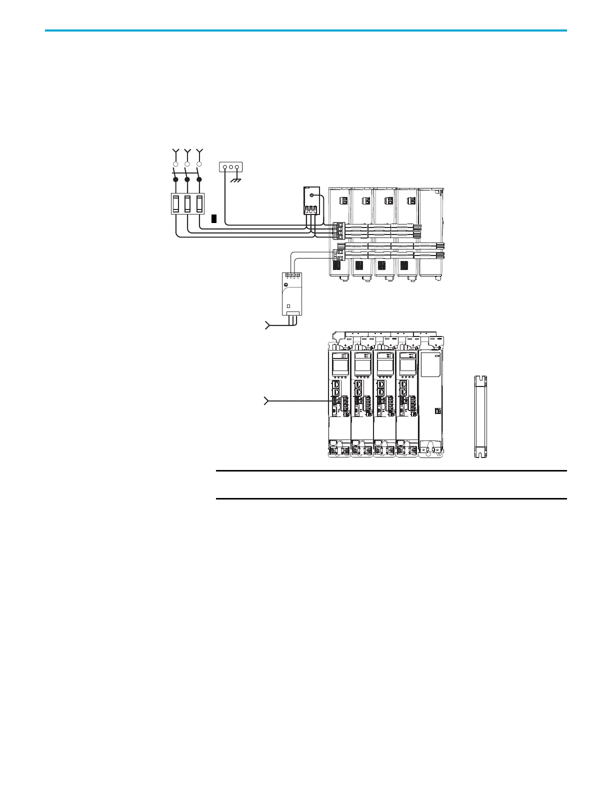
Shared AC/DC Configurations
In this example, three-phase AC input power, 24V control power, and DC-bus
power are shared in a multi-axis configuration. All drives must be the same
power rating (catalog number).
Figure 3 - Typical Shared AC/DC Installations
1606-XL
Power Supply
Input
Allen-Bradley
2097-Rx
Shunt Resistor
(optional component)
Line
Disconnect
Device
Input
Fusing
Three-phase
Input Power
AC Input Power
Bonded Cabinet
Ground Bus
2198-DBRxx-F
AC Line Filter
(can be required for
CE and UK)
Kinetix 5500 Servo Drives (top view)
(2198-H015-ERS drives shown)
Kinetix 5500 Servo Drives (front view)
(2198-H015-ERS drives shown)
Shared AC (mains AC input)
Shared DC (DC common bus)
Shared 24V (control power input)
2198-CAPMOD-1300 Capacitor Module
(optional component)
Shared-bus connection system for
bus-sharing configurations.
Digital Inputs
to Sensors and Control String
1606-XLxxx
24V DC Control, Digital Inputs,
and Motor Brake Power
(customer-supplied)
IMPORTANT In shared AC/DC configurations, all drives must have the same power
rating (catalog number).

 Loading...


