72 Rockwell Automation Publication 2198-UM001M-EN-P - November 2022
Chapter 5 Connect the Kinetix 5500 Drive System
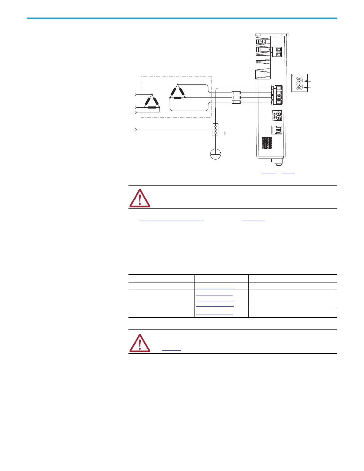
Figure 41 - Ungrounded Power Configuration
(1) The AC ground jumper is removed and the DC ground jumper is removed. See Figure 42 on page 73 for access to ground
screws.
See Power Wiring Examples beginning on page 180 for input power
interconnect diagrams.
Ground Screw Settings Determine the ground screw setting for your Kinetix 5500 servo drives.
Transformer
Three-phase
Input VAC
Chassis Ground
Bonded Cabinet Ground
Ground Grid or
Power Distribution Ground
Connect to
Ground Stud
Kinetix 5500 Servo Drive
(top view)
Circuit
Transformer (Delta) Secondary
AC Screw
(1)
DC Screw
ATTENTION: Ungrounded systems do not reference each phase potential to
a power distribution ground. This can result in an unknown potential to
earth ground.
Table 35 - Ground Screw Settings
Ground Configuration Example Diagram Ground Screw Setting
Grounded (wye) Figure 37 on page 69
Both screws installed (default setting)
• AC fed ungrounded
• Corner grounded
• Impedance grounded
Figure 41 on page 72
Figure 39 on page 70
Figure 38 on page 70
Both screws removed
Single-phase input power Figure 40 on page 71
AC screw removed
(1)
(1) Removing the AC ground screw to minimize leakage current in single-phase operation can affect EMC performance.
ATTENTION: To help prevent damage to the servo drive, you must set the
ground screws according to the example diagrams that are summarized in
Table 35.

 Loading...


