Rockwell Automation Publication 2198-UM001M-EN-P - November 2022 61
Chapter 4 Connector Data and Feature Descriptions
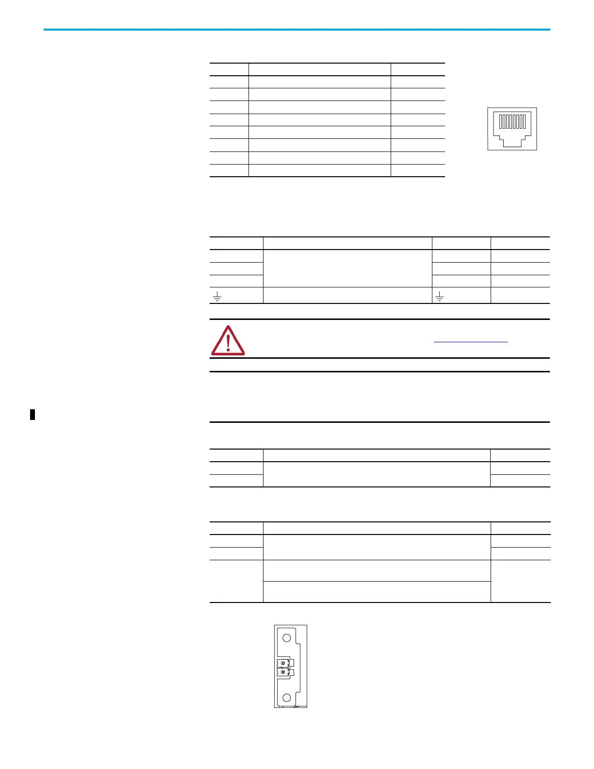
Ethernet Communication Connector Pinout
Motor Power, Brake, and Feedback Connector Pinouts
Motor Feedback Connector Pinout
Figure 33 - Pin Orientation for Motor Feedback (MF) Connector
Pin Description Signal
1Transmit+ TD+
2Transmit- TD-
3 Receive+ RD+
4 Reserved —
5 Reserved —
6 Receive- RD-
7 Reserved —
8 Reserved —
Table 28 - Motor Power Connector
MP Pin Description Signal Color
U
Three-phase motor power
UBrown
VVBlack
WWBlue
Chassis ground Green
ATTENTION: To avoid damage to the Kinetix 5500 drive, make sure that the
moSeer power signals are wired correctly. See Figure 50 on page 81 for
motor power connector wiring examples.
IMPORTANT Drive-to-motor power cables must not exceed 50 m (164 ft), depending
on overall system design.
System performance was tested at this cable length. These limitations
also apply when meeting CE and UK requirements.
Table 29 - Motor Brake Connector
BC Pin Description Signal
1
Motor brake connections
MBRK+
2MBRK-
MF Pin Description Signal
1
Bidirectional data and power for digital encoder interface
D+
2D-
SHIELD
Cable shield and grounding plate (internal to 2198-KITCON-DSL connector
kit) termination point
SHIELD
Cable shield and shield clamp (internal to 2198-H2DCK converter kit)
termination point
1
8

 Loading...


