184 Rockwell Automation Publication 2198-UM001M-EN-P - November 2022
Appendix A Interconnect Diagrams
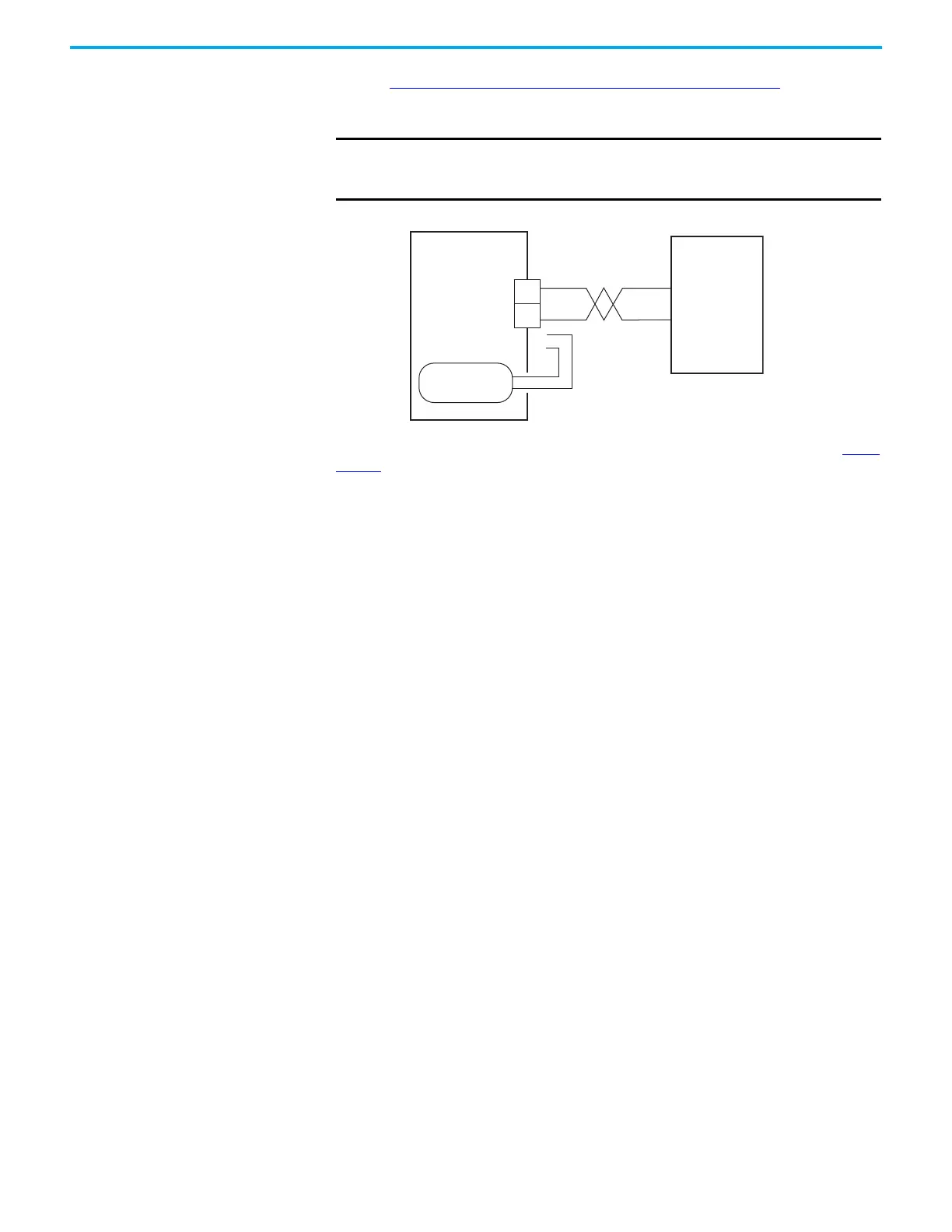
Shunt Resistor Wiring
Example
See the External Passive-shunt Resistor Connections on page 97 for the
Bulletin 2097 external shunt resistor catalog numbers available for
Kinetix 5500 servo drives.
Figure 96 - Shunt Resistor Wiring Example
See the Kinetix 300 Shunt Resistor Installation Instructions, publication 2097-
IN002, for shunt resistor installation instructions.
IMPORTANT Before wiring the Bulletin 2097 external shunt to the RC connector,
remove the wires from the servo drive internal shunt. Do not connect
internal and external shunt resistors to the drive.
2198-Hxxx-ERSx
Kinetix 5500 Drive
2097-Rx
Shunt Resistor
Shunt (RC)
Connector
Internal Shunt

 Loading...


