80 Rockwell Automation Publication 2198-UM001M-EN-P - November 2022
Chapter 5 Connect the Kinetix 5500 Drive System
Wire the Digital Input
Connectors
This section provides guidelines to assist you in making digital input
connections.
Wire the Safe Torque Off Connector
For the hardwired Safe Torque Off (STO) connector pinouts, feature
descriptions, and wiring information, see Chapter 9 beginning on page 157.
Wire the Digital Inputs Connector
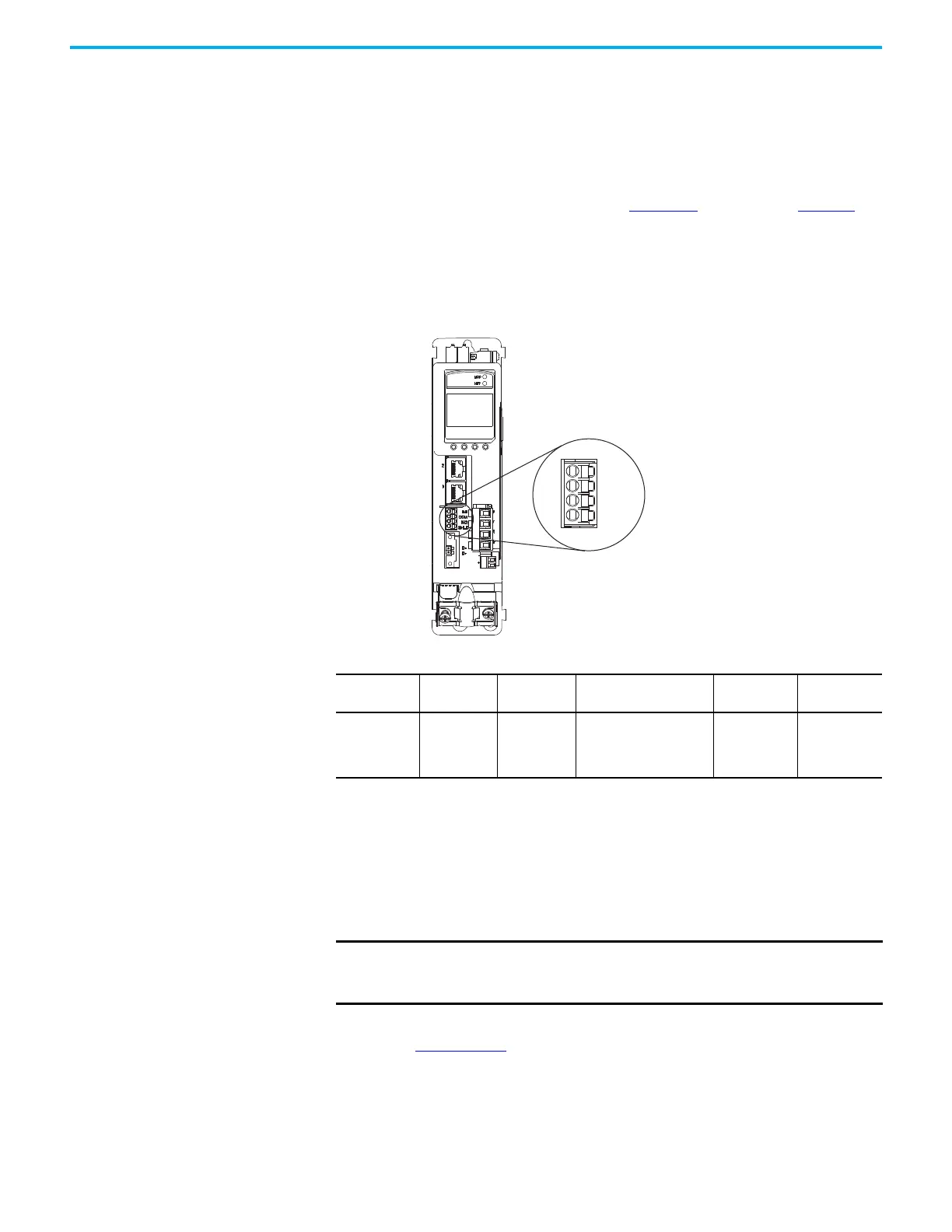
The digital inputs (IOD) connector uses spring tension to hold wires in place.
Figure 49 - IOD Connector Wiring
Wire Kinetix VP Motors and
Actuators
Kinetix 5500 drives and Kinetix VP motor/actuator combinations use single
motor-cable technology with motor power, feedback, and brake wires (when
specified) housed in a single cable. Feedback wires are shielded separately and
provide a shield braid for grounding in the connector kit.
See the Kinetix Rotary and Linear Motion Cable Specifications Technical Data,
publication KNX-TD004
, for cable specifications.
Digital Inputs (IOD) Connector Plug
Kinetix 5500 Servo Drive
(front view)
Table 41 - Digital Inputs (IOD) Connector Specifications
Drive Cat. No. DC Pin Signal
Recommended Wire Size
mm
2
(AWG)
Strip Length
mm (in.)
Torque Value
N•m (lb•in)
2198-Hxxx-ERSx
IOD-1
IOD-2
IOD-3
IOD-4
IN1
(1)
COM
IN2
SHLD
(1) This signal has dual-functionality. You can use IN1 (IOD-1) as registration or Home input.
0.2…1.5
(24…16)
10.0 (0.39)
—
(2)
(2) This connector uses spring tension to hold wires in place.
IMPORTANT Due to the unique characteristics of single cable technology, which is
designed for and tested with Kinetix 5500 drives and Kinetix VP
motors, you cannot build your own cables or use third-party cables.

 Loading...


