206 Rockwell Automation Publication 2198-UM001M-EN-P - November 2022
Appendix C Size Multi-axis Shared-bus Configurations
Power-sharing Sizing
Examples
For best results, size motors based on load torque requirements by using
Motion Analyzer Online. Select drives based on continuous or peak torque
requirements. Based on the load profile, use Motion Analyzer Online to
estimate the net converter and inverter power and bus regulator capacity.
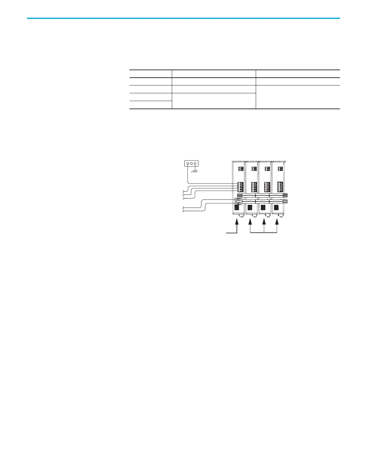
Shared DC Example
In this example, four 2198-H040-ERS drives are used in a common-bus
configuration.
Figure 110 - DC Common Bus Configuration
Each 2198-H040-ERS drive is rated at 8.4 kW continuous output power to the
bus. However, only the leader drive acts as the converter, so the available
converter power to the system is 8.4 kW. In this example, total motoring load
must not exceed 8.4 kW.
Table 85 - Converter and Bus Regulator Capacity
Configuration Available Converter Capacity Available Regenerative Capacity
Shared AC Converter power rating of each drive Internal shunt of each drive
Common bus Converter power rating of leader drive
Sum of all internal shunts from each drive in
bus-sharing group
Shared AC/DC
Sum of converter power ratings times 0.7
(70%)
Shared AC/DC hybrid
Bonded Cabinet
Ground
Three-phase
Input Power
24V Input
Control Power
2198-H040-ERS
Common-bus Leader Drive
2198-H040-ERS
Common-bus
Follower Drives
DC Bus Connections

 Loading...


