42 Rockwell Automation Publication 2198-UM001M-EN-P - November 2022
Chapter 2 Plan the Kinetix 5500 Drive System Installation
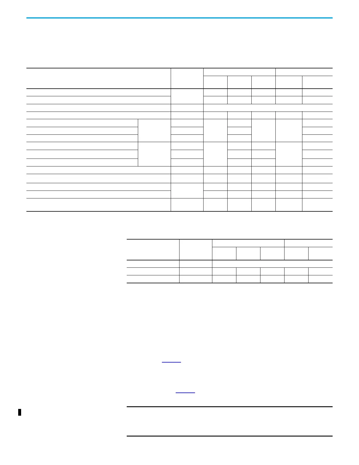
Cable Categories for Kinetix 5500 Systems
These tables indicate the zoning requirements of cables connecting to the
Kinetix 5500 drive components.
Noise Reduction Guidelines for Drive Accessories
See this section when mounting an AC (EMC) line filter or external
passive-shunt resistor for guidelines that are designed to reduce system
failures caused by excessive electrical noise.
AC Line Filters
Observe these guidelines when mounting your AC (EMC) line filter (refer to
the figure on page 41
for an example):
• Mount the AC line filter on the same panel as the Kinetix 5500 drive and
as close to the drive as possible.
• Good HF bonding to the panel is critical. For painted panels, refer to the
examples on page 39
.
• Separate input and output wiring as far as possible.
Table 18 - Kinetix 5500 Drive
Wire/Cable Connector
Zone Method
Very Dirty Dirty Clean
Ferrite
Sleeve
Shielded Cable
L1, L2, L3 (shielded cable)
IPD
—X —— X
L1, L2, L3 (unshielded cable) X — — — —
DC-/DC+ (DC bus) DC Busbar only, no wiring connector.
DC+/SH (shunt) RC — X — — —
U, V, W (motor power)
Kinetix VP
motors/
actuators
MP
—
X
——
X
Motor feedback MF X X
Motor brake BC X X
U, V, W (motor power)
Kinetix MP
motors/
actuators
MP
—
X—
—
X
Motor feedback
(1)
MF — X X
Motor brake BC X — X
24V DC CP — X — — —
Safety enable for Safe Torque Off (hardwired)
(2)
STO — X — — —
Registration input
IOD
——X — X
Dedicated digital inputs (other than registration inputs) — X — — —
Ethernet
PORT1
PORT2
——X — X
(1) When the 2198-H2DCK converter kit is used, the feedback cable routes in the clean wireway.
(2) STO connector applies to only 2198-Hxxx-ERS (hardwired) servo drives.
Table 19 - Capacitor Module
Wire/Cable Connector
Zone Method
Very Dirty Dirty Clean
Ferrite
Sleeve
Shielded
Cable
DC-/DC+ (DC bus) DC Busbar only, no wiring connector.
24V DC CP — X — — —
Module status MS — X — — —
IMPORTANT CE and UK test certification applies to only the AC line filter used with a
single drive or the line filter used in multi-axis drive configurations.
Sharing a line filter with more than one multi-axis drive configuration
can perform satisfactorily, but the customer takes legal responsibility.

 Loading...


