Rockwell Automation Publication 2198-UM001M-EN-P - November 2022 71
Chapter 5 Connect the Kinetix 5500 Drive System
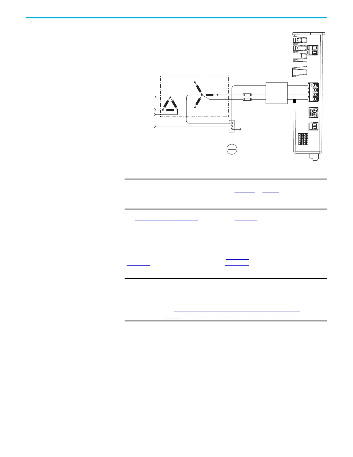
Figure 40 - Grounded Power Configuration (Single-phase Input)
(1) When using a 2198-DBxx-F line filter, the AC ground jumper is installed and the DC ground jumper is installed. When using
a 2198-DBRxx-F line filter, the AC ground jumper is installed and the DC ground jumper is installed.
See Power Wiring Examples beginning on page 180 for input power
interconnect diagrams.
Ungrounded Power Configurations
The ungrounded power configuration (Figure 41), corner-grounded
(Figure 39), and impedance-grounded (Figure 38) power configurations do not
provide a neutral ground point.
L2
L1
1
2
L3
L2
L1
1
2
L3
Transformer
Three-phase
Input VAC
Phase Ground
Transformer (wye) Secondary
Bonded Cabinet Ground
Ground Grid or
Power Distribution Ground
Kinetix 5500 Servo Drive
(top view)
Circuit
Connect to
Ground Stud
Three-phase
(1)
AC Line Filter
(can be required
for CE and UK)
IMPORTANT To reduce leakage current in single-phase AC input operation, remove
the AC ground screw (refer to Figure 42 on page 73).
Install the AC ground screw only if higher EMC performance is
required.
IMPORTANT If you determine that you have ungrounded, corner-grounded, or
impedance-grounded power distribution in your facility, you must
remove the ground screws in each of your drives that receive input
power.
See Remove the Ground Screws in Select Power Configurations
on
page 73 for more information.

 Loading...


