4. Remove the internal braking resistor connection from the terminal block DCP/PB in the Wiring
Module, and insulate the cable conductors with the heat-shrinkable tube.
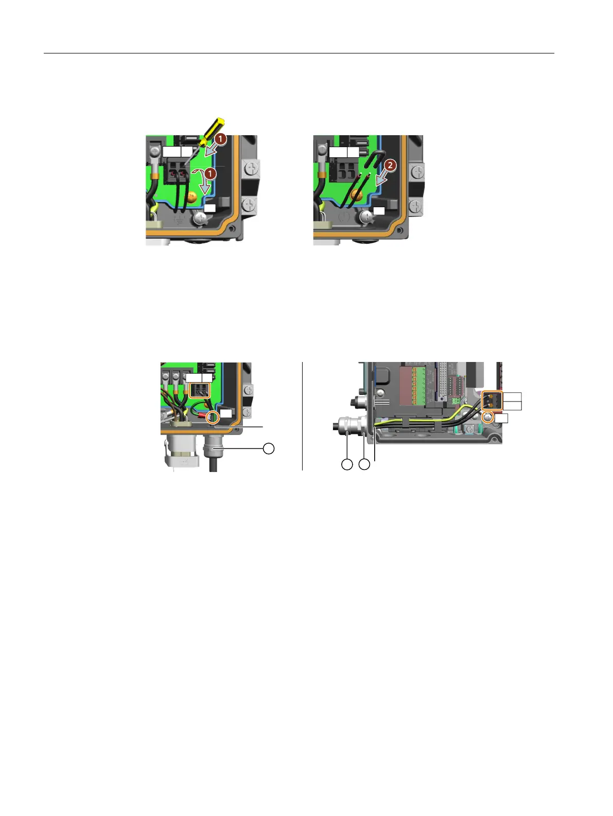
5. Remove the blanking cap at interface X4 and install the M16 cable gland.
– For the G115D wall-mounted converter, directly install the M16 cable gland ① at
interface X4. If you do not use the provided cable gland, make sure that the thread length
of the cable gland you use is no more than 9 mm.
– For the G115D motor-mounted converter, rstly install the M16 reducer ② at interface
X4, and then install the M16 cable gland ① on the M16 reducer.
(%.PUPS.PVOUFE(%8BMM.PVOUFE
9
9
1#
1&
%$1
1#
1&
%$1
6. Remove the insulation from the end of the braking resistor cable to expose the braided cable
shield. Turn up the cable shield. Pass the cable through the cable gland and make the exposed
braided cable shield in close contact with the inner surface of the cable gland. Make sure that
the cable shield is connected to the shield bonding options for cables and the unit housing
respectively with excellent electrical conductivity and a large contact area.
7. Connect the external braking resistor cable to the terminal block DCP/PB and the PE terminal.
8. Re-attach the Electronic Module with a tightening torque of 2.5 Nm (22.1 lbf.in).
❒
Wiring
5.17Connecting the external braking resistor
SINAMICS G115D Wall Mounted distributed drive
102 Operating Instructions, 07/2023, FW V4.7 SP14, A5E52808211A AA

 Loading...


