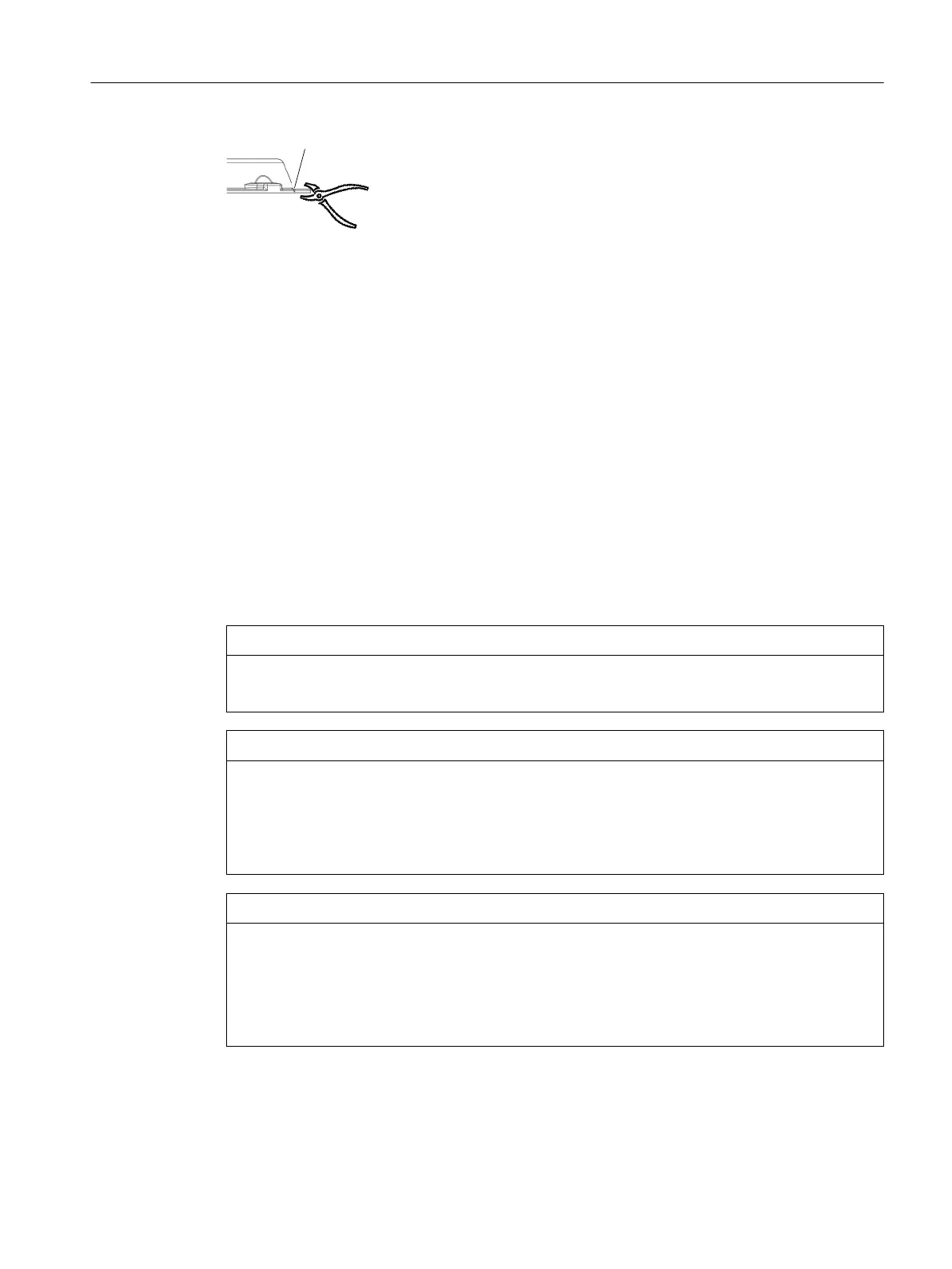
* Preset breaking point
Figure12-19 Preset breaking point for F49
1. F49: Break the cover at the preset breaking point as shown in the diagram.
2. Mount the output shaft.
3. Use a suitable cleaning agent to clean the contact surface of the protection cover ② on the
gearbox.
4. Ensure that the O-ring or at seal③ is correctly seated.
5. Screw on the protective cover② with a tightening torque of 10‑15Nm.
6. Protect all remaining bare areas with a suitable permanent anti-corrosive agent.
You have now mounted the plastic protection cover for operation.
12.3.13 General information on installing the shaft-mounted gearbox
NOTICE
Damage to shaft sealing rings caused by solvent
Avoid any contact of solvent or benzine with the shaft sealing rings.
NOTICE
Subjecting stress to the hollow shaft causes bearing failure
Skewing or stressing the hollow shaft increases the loading. This can cause bearing failure.
The hollow shaft must be ush with the machine shaft to avoid misalignment.
Do not subject the hollow shaft to axial and radial stress.
NOTICE
For shrink disks:
Lubricants in the area between the hollow shaft and machine shaft impair torque
transmission
Keep the bore in the hollow shaft and the machine shaft completely grease-free.
Do not use impure solvents and soiled cleaning cloths.
Additional information on the SIMOGEAR geared motor
12.3Specic data gearbox
SINAMICS G115D Wall Mounted distributed drive
Operating Instructions, 07/2023, FW V4.7 SP14, A5E52808211A AA 491
 Loading...


