Parameter Description Setting
p0610[0...n] Motor overtemperature response Sets the system response when the motor temper‐
ature reaches the alarm threshold.
0: A07012, not reducing the current limit.
1: A07012 and F07011, reducing the current limit.
2: A07012 and F07011, not reducing the current
limit.
12: A07012 and F07011, not reducing the current
limit. (factory setting)
Note: After setting p0610 = 12 and switching o
the supply voltage, the converter saves the most
recently calculated dierence to the ambient air
temperature. After switching the supply voltage on
again, the thermal motor model starts with 90 % of
the previously saved dierence temperature.
p0640[0...n] Current limit [A] Sets the current limit.
Factory setting: 0
Additional information on the motor temperature monitoring can be found in function
diagram 8016 of the List Manual.
7.25 Motor protection by calculating the temperature
Overview
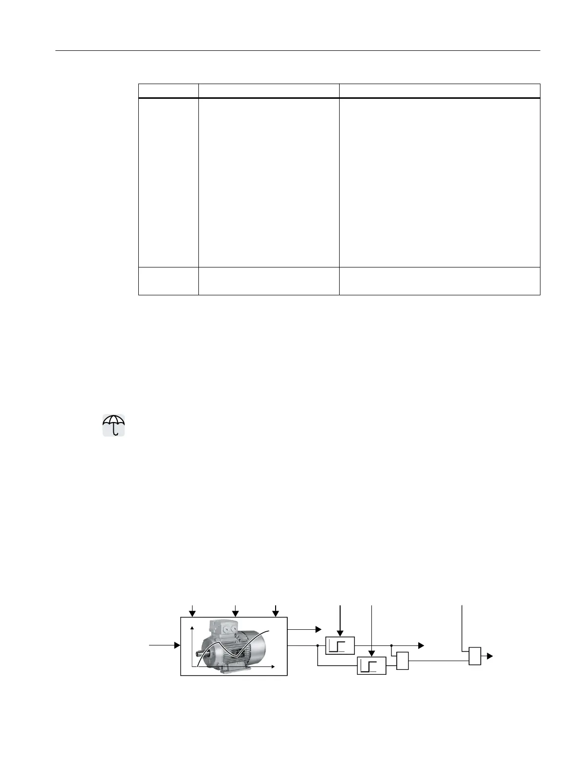
The converter calculates the motor temperature based on a thermal motor model.
The thermal motor model responds far faster to temperature increases than a temperature
sensor.
If the thermal motor model is used together with a temperature sensor, e.g. a Pt1000, then
the converter corrects the model according to the measured temperature.
Function description
Thermal motor model 2 for asynchronous motors
The thermal motor model 2 for asynchronous motors is a thermal 3-mass model, consisting
of stator core, stator winding and rotor. Thermal motor model2 calculates the temperatures -
both in the rotor as well as in the stator winding.
ุ
W
˽
˽U
SSS
SS!
S
$
)
U
L
U
Advanced commissioning
7.25Motor protection by calculating the temperature
SINAMICS G115D Wall Mounted distributed drive
Operating Instructions, 07/2023, FW V4.7 SP14, A5E52808211A AA 323
 Loading...


