12.3.8 Gearbox with foot mounting
The foundation should be designed in such a way that no resonance vibrations are created and
no vibrations are transmitted from adjacent foundations.
The foundation structure on which the gearbox is to be mounted must be torsionally
rigid. It must be dimensioned according to the weight and torque, taking into account the
forces acting on the gearbox. If the substructure is too weak, it will cause radial or axial
displacement oset during operation that cannot be measured at a standstill.
If the gearbox is fastened to a concrete foundation, use foundation blocks for the appropriate
recesses.
Align and grout the slide rails into the foundation.
Align the gearbox carefully with the units on the input and output side. Take into account the
elastic deformation due to operating forces.
Prevent displacement from external forces due to lateral impacts.
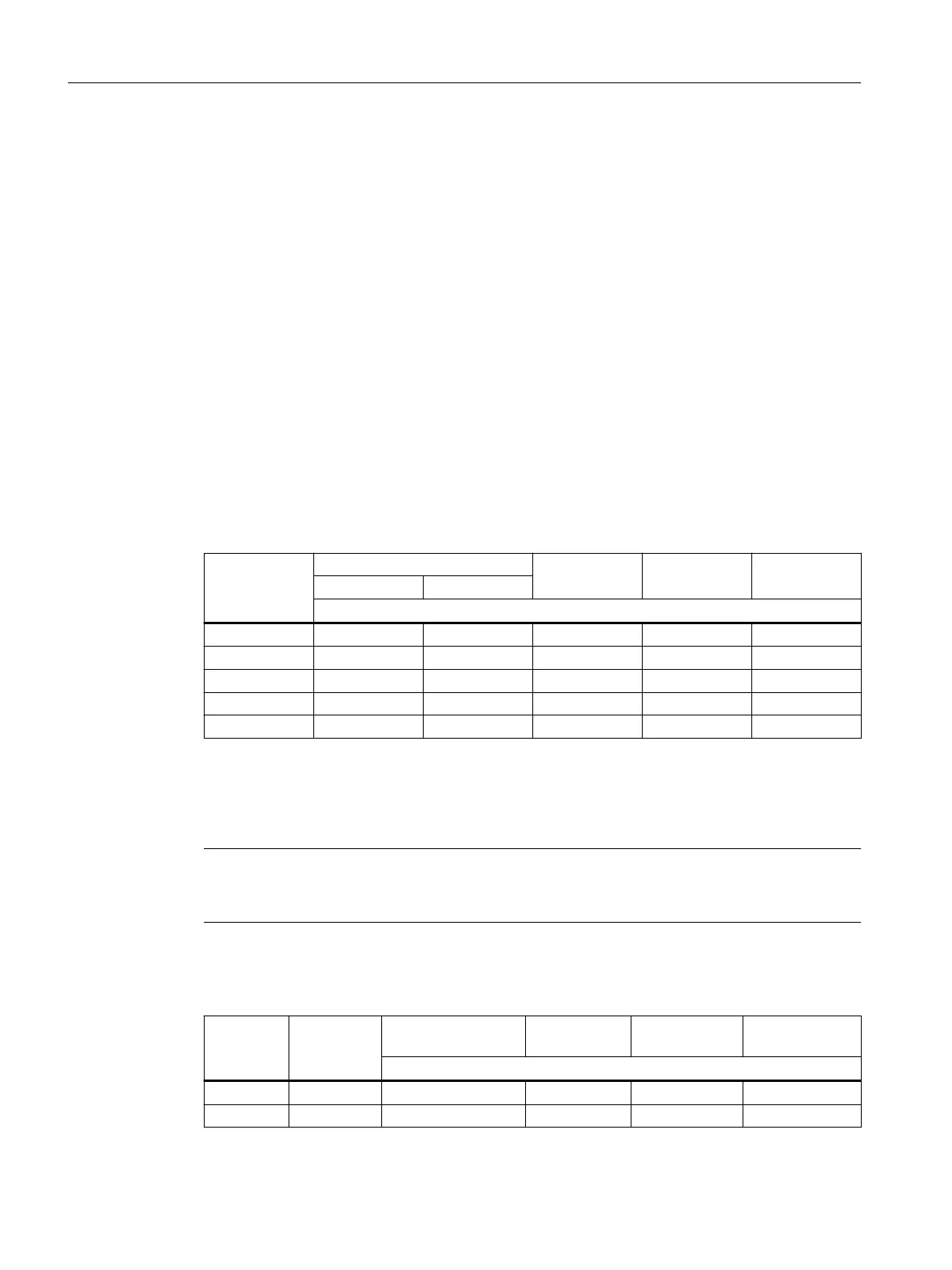
Use stud bolts or headless screws of property class8.8 or higher for the mounting foot.
Observe the tightening torque.
Table 12-30 Thread size of the xing screw
Thread size Helical gearbox Parallel shaft
gearbox F
Bevel gearbox
B,K
Helical worm
gearboxC
E D/Z
Size
M8 ‑ 19, 29, 39 29, 39 B19, B29, B39 29
M10 39 ‑ 49 B49, K39, K49 39, 49
M12 49 49, 59, 69 69, 79 K69, K79 69
M16 69, 89 79, 89 89 K89 89
M20 ‑ ‑ ‑ K109 ‑
12.3.9 Gearbox with ange mounting
Note
Siemens recommends an anaerobic adhesive to enhance the friction lock between ange and
mounting surface.
Table 12-31 Thread size of the xing screw
Thread
size
Flange Helical gearbox
E, D/Z
Parallel shaft
gearbox F
Bevel gearbox
B,K
Helical worm
gearboxC
Size
M6 A120 19,29,39 29 B19,B29 29
M8 A140,A160 19,29,39,49,59 29,39 B29,B39,K39 29,39
Additional information on the SIMOGEAR geared motor
12.3Specic data gearbox
SINAMICS G115D Wall Mounted distributed drive
486 Operating Instructions, 07/2023, FW V4.7 SP14, A5E52808211A AA
 Loading...


