Note
Coat the contact surfaces with the mounting paste supplied with the product or any suitable
lubricant to prevent frictional corrosion.
Note
Observe the permissible concentricity tolerance of the cylindrical shaft extension of the
machine shaft to the housing axle according to DIN42955.
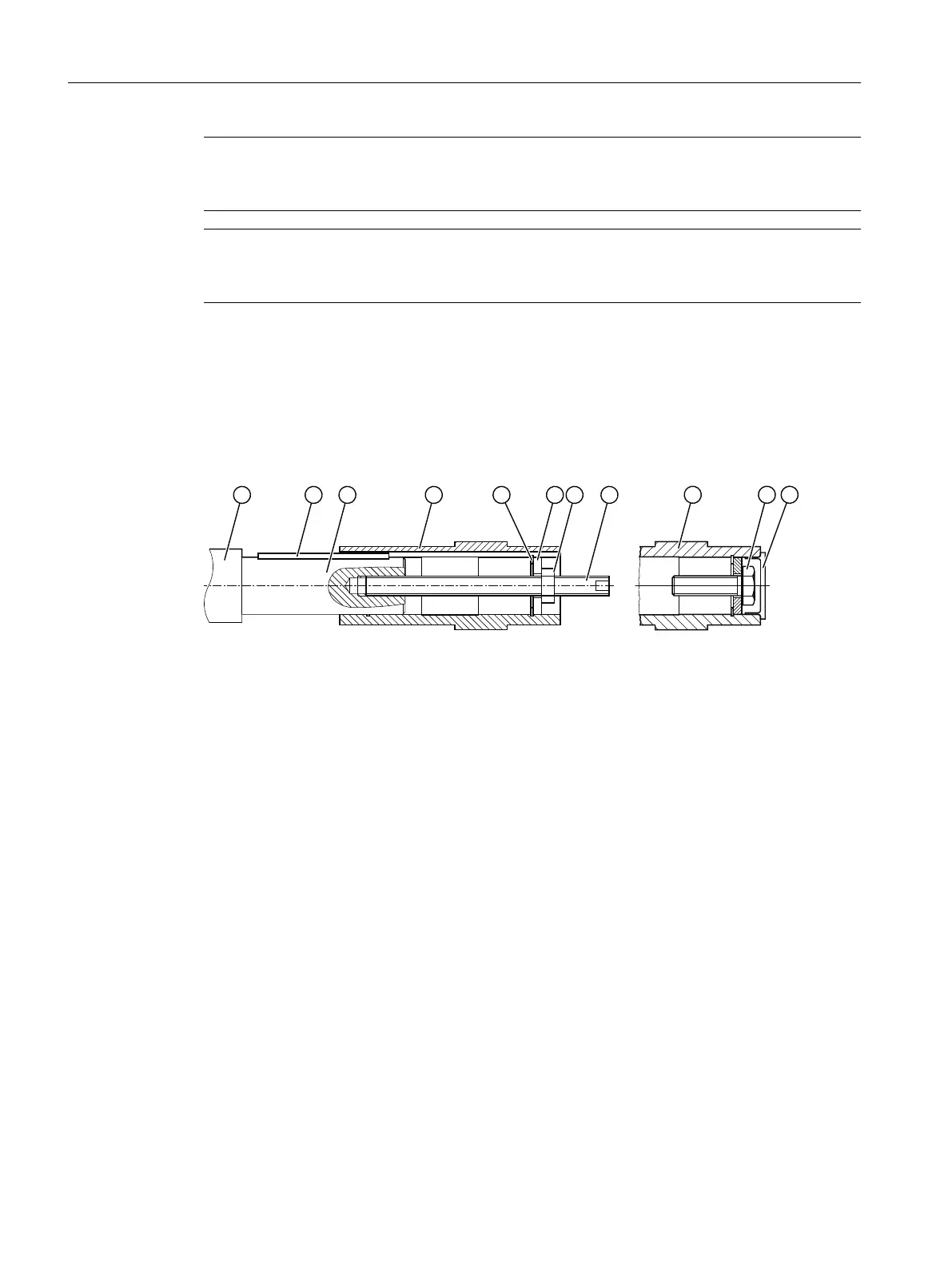
12.3.14 Hollow shaft with feather key
12.3.14.1 Mounting the hollow shaft with parallel key
* Not included in scope of supply
① Machine shaft ⑥ Locking ring
② Hollow shaft ⑦ Parallel key
③ Hexagon nut ⑧ Mounting paste
④ Threaded spindle ⑨ Screw
⑤ Disk ⑩ Sealing cap
Figure12-20 Mounting the hollow shaft with parallel key
Instead of the nut and threaded spindle shown in the diagram, other types of equipment
such as hydraulic lifting equipment may be used.
Procedure
1. Using benzine or a solvent, remove the anti-corrosion protection from the shaft ends and
anges.
2. Check the seats or edges of the hollow and machine shafts for any damage. Contact
Technical Support if you notice any damage.
3. Apply the mounting paste provided ① to the machine shaft ⑧. Apply the paste uniformly.
Carefully wipe away the rest at the shaft sealing ring of the gearbox.
4. Fit the gearbox using the disk ⑤, threaded spindle ④ and nut ③. Use the hollow shaft ②
for support.
Additional information on the SIMOGEAR geared motor
12.3Specic data gearbox
SINAMICS G115D Wall Mounted distributed drive
492 Operating Instructions, 07/2023, FW V4.7 SP14, A5E52808211A AA
 Loading...


