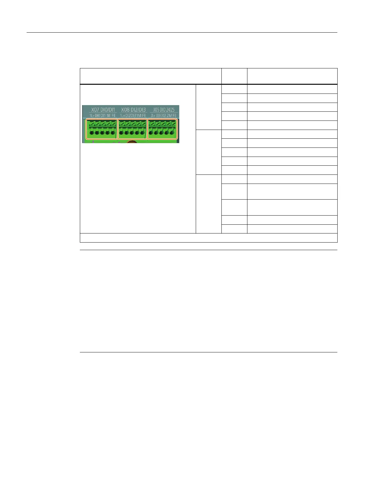
Glanded variant
Digital inputs (X07, X08) and bidirectional digital in‐
puts/outputs (X05)
Signal Description
X07 1L+ Unswitched 24 V
DI0 Digital input 0
DI1 Digital input 1
1M Unswitched 0 V
FE Functional earth
X08 1L+ Unswitched 24 V
DI2 Digital input 2
DI3 Digital input 3
1M Unswitched 0 V
FE Functional earth
X05 2L+ Switched 24 V
DIO24 Bidirectional digital output/input
24
DIO25 Bidirectional digital output/input
25
2M Switched 0 V
FE Functional earth
Cable gland size: M16 * 1.5; Tightening torque: 10Nm/88.5lbf.in
Note
Malfunction caused by incorrect switching states as the result of diagnostic ows in o
state (logical state "0")
In contrast to mechanical switching contacts, e.g. emergency stop switches, diagnostic ows
can also ow with semiconductor switches in the o state. If interconnection with digital inputs
is faulty, the diagnostic ows can lead to incorrect switching states and thus to a malfunction of
the drive.
• Observe the conditions for digital inputs and digital outputs specied in the relevant
manufacturers documentation.
• Check the conditions of the digital inputs and digital outputs in regard to the ows in o
state. If applicable, connect the digital inputs with suitably dimensioned, external resistors
to protect against the reference potential of the digital inputs.
5.12.2 Factory interface setting
To ensure that the factory setting of the interfaces can be used, you must wire your drive as
shown in the following examples.
Wiring
5.12Connecting the digital inputs and outputs
SINAMICS G115D Wall Mounted distributed drive
82 Operating Instructions, 07/2023, FW V4.7 SP14, A5E52808211A AA
 Loading...


