If the motor load is so high during steady-state operation that the motor current reaches the
current limit, then the I_max controller reduces the speed and the motor voltage until the
motor current returns to the permissible range again.
If the motor current reaches the current limit during deceleration, the I_max controller
extends the deceleration operation.
Parameters
The factory setting for proportional gain and the integral time of the I_max controller ensures
faultless operation in the vast majority of cases.
The factory setting of the I_max controller must only be changed in the following exceptional
cases:
• Speed or torque of the motor tend to cause vibrations upon reaching the current limit.
• The converter goes into the fault state with an overcurrent message.
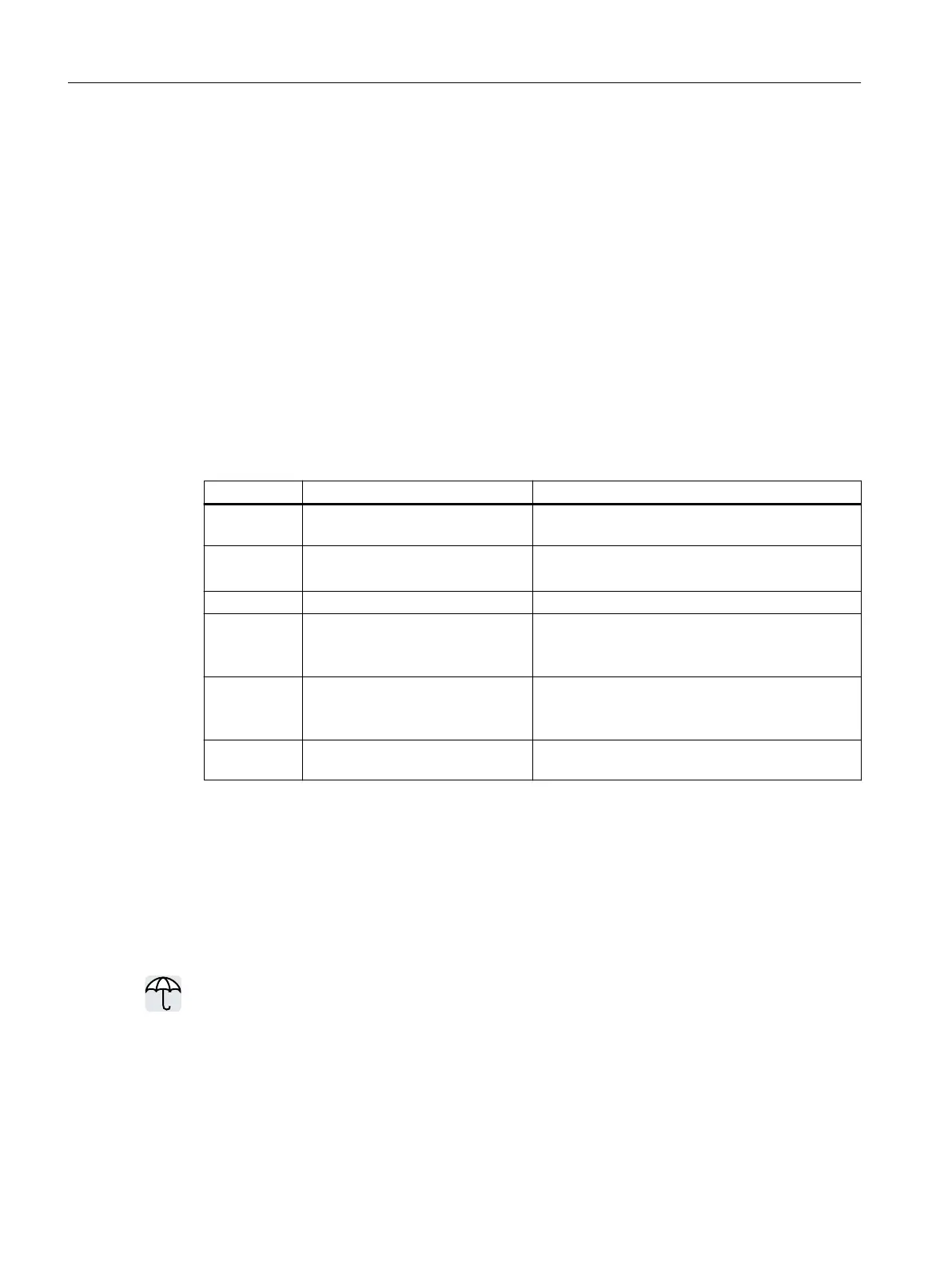
Parameter Description Setting
r0056.0…15 CO/BO: Status word, closed-loop
control
Display and BICO output for the status word of the
closed-loop control.
p0305[0...n] Rated motor current [A] Sets the rated motor current.
Factory setting: 0
p0640[0...n] Current limit [A] Sets the current limit.
p1340[0...n] I_max frequency controller propor‐
tional gain
Sets the proportional gain of the I_max frequency
controller.
Factory setting: 0
p1341[D] I_max frequency controller inte‐
gral time [s]
Sets the integral time for the I_max frequency con‐
troller.
Factory setting: 0.3
r1343 CO: I_max controller frequency
output [rpm]
Displays the eective frequency limit.
You will nd more information about this function in function diagram 6300 and in the
parameter list.
7.23 Converter protection using temperature monitoring
Overview
The converter temperature is essentially dened by the following eects:
• The ambient temperature
• The ohmic losses increasing with the output current
• Switching losses increasing with the pulse frequency
Advanced commissioning
7.23Converter protection using temperature monitoring
SINAMICS G115D Wall Mounted distributed drive
316 Operating Instructions, 07/2023, FW V4.7 SP14, A5E52808211A AA