Gearbox Size Hollow
shaft ∅
b10 b11 b12 d10 d11 s11 t
max
u
mm mm mm mm mm mm mm mm mm
K, F, C 69 40 6 20 9 39.9 28 M16 43 12
C 45 6 20 9 44.9 36 M16 48 14
K, F 79 40 6 20 9 39.9 28 M16 43 12
K, F, C 89 50 7 20 10 49.9 36 M16 53.5 14
C 60 7 20 10 59.9 45 M20 64 18
K 109 60 10 24 14 59.9 45 M20 64 18
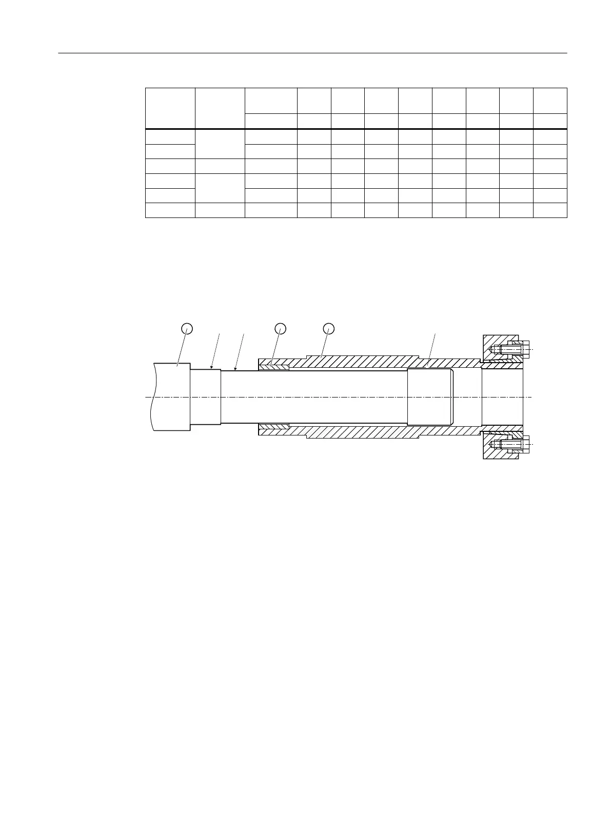
12.3.15 Hollow shaft with shrink disk
12.3.15.1 Mounting the hollow shaft with shrink disk
a Greased
b Absolutely grease-free
① Machine shaft
② Hollow shaft
③ Bushing
Figure12-22 Mounting the hollow shaft with shrink disk
Procedure
1. Using benzine or a solvent, remove the anti-corrosion protection from the shaft ends and
anges.
2. Check the seats or edges of the hollow and machine shafts for any damage. Contact
Technical Support if you notice any damage.
3. Mount the gearbox with the shrink disk shaft onto the machine shaft. Carefully ensure the
correct position and that the shrink disk seat completely covers the machine shaft.
You have mounted the hollow shaft with shrink disk.
Additional information on the SIMOGEAR geared motor
12.3Specic data gearbox
SINAMICS G115D Wall Mounted distributed drive
Operating Instructions, 07/2023, FW V4.7 SP14, A5E52808211A AA 495
 Loading...


