4FUQPJOUGSPN1PUFOUJPNFUFS
5HYHUVH
21
(QDEOH2))
$FNQRZOHGJHIDXOW
$ODUP
)DXOW
1
',
',
',
',
;
;
;
',2
',2
Further information
You can adjust the default interface settings to suit your requirements.
Adapt the default settings of the inputs and outputs (Page133)
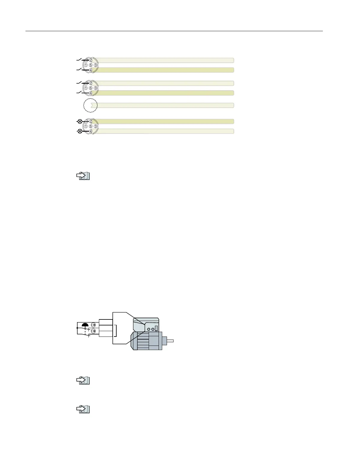
5.12.3 Fail-safe digital input
To enable a safety function via the terminal strip of the converter, you need a fail-safe digital
input. The digital inputs DI 2 and DI 3 can be used for the safety functions.
In the factory setting of the converter, the fail-safe digital input is not assigned to the
integrated safety functions. Only when commissioning do you dene as to whether, for
example, you use digital inputs for the standard functions, or you create a fail-safe digital
input by combining them.
Wiring examples
An example for wiring the fail-safe digital input corresponding to PL d according to EN 13849-1
and SIL 2 according to IEC 61508 is given below:
;
6,1$0,&6*'
)',
',
',
/
Further information
Safe Torque O (STO) safety function (Page233)
Additional congurations of the safety functions are described in the "Safety Integrated"
Function Manual.
Overview of the manuals (Page588)
Wiring
5.12Connecting the digital inputs and outputs
SINAMICS G115D Wall Mounted distributed drive
88 Operating Instructions, 07/2023, FW V4.7 SP14, A5E52808211A AA
 Loading...


