WARNING
Fire after short-circuit in the motor current circuit caused by rotating permanent magnet
synchronous motor
In the event of a short circuit in the converter or in the motor cable, a permanent magnet
synchronous motor supplies energy to the short-circuit as long as the motor is rotating. This can
cause smoke and a re, endangering people.
• Install a contactor between the motor and the converter and as close to the motor as
possible.
• Use a contactor with overvoltage protection to prevent damage to the motor when
separating the motor from the converter.
• Use converter signal r0863.1 and a free digital output of the converter to open the contactor
between motor and converter in the event of a fault.
5.10.1 Interface description - X2
The motor power interface located on the Wiring Module is available only for the G115D wall-
mounted converter. For a G115D converter with SIMOGEAR geared motor, the wiring between
the converter and the motor is completed when delivered.
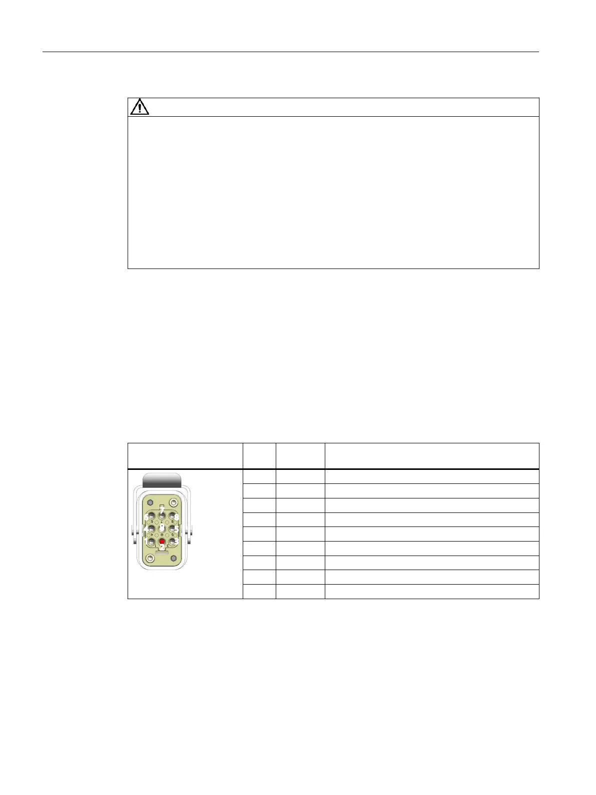
Connector variant
Q8/0 connector
X2 - motor power, 8-pin,
female
Pin Signal Description
1 U Phase U
2 - Not connected
3 W Phase W
4 EM-/EM2 EM brake negative (180 V DC) / EM brake 2 (400 V AC)
5 T+ Motor temperature sensor positive
6 EM+/EM1 EM brake positive (180 V DC) / EM brake 1 (400 V AC)
7 V Phase V
8 T- Motor temperature sensor negative
9 PE Protective earth
Wiring
5.10Connecting the motor
SINAMICS G115D Wall Mounted distributed drive
74 Operating Instructions, 07/2023, FW V4.7 SP14, A5E52808211A AA
 Loading...


