Function description
Procedure
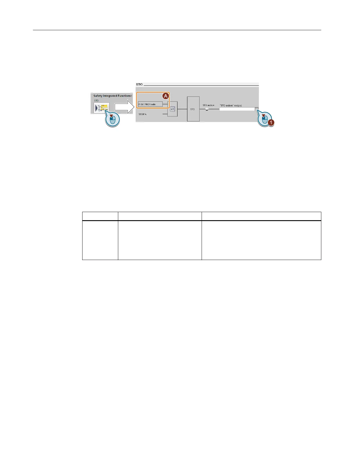
1. Select the button for the feedback signal.
The screen form varies depending on the interface selected.
(A) Control type
2. Select the signal that matches your particular application.
You have interconnected the "STO active" checkback signal.
❒
After STO has been selected, the converter signals "STO active" to the higher-level control.
Parameters
Parameter Description Setting
r9773.0...31 CO/BO: SI status (processor 1 + pro‐
cessor 2)
Display and BICO output for the Safety Integrated
status on the drive (processor 1 + processor 2).
Bit 0: STO is selected in the drive
Bit 1: STO is active in the drive
Bit 31: Test stop is required for STO
7.15.2.5 Setting the lter for fail-safe digital inputs
Overview
The following lters are available for the fail-safe digital inputs:
• A lter for the simultaneity monitoring
• A lter for suppressing short signals, e.g. test pulses.
Function description
Discrepancy time for the simultaneity monitoring
The converter checks that the two input signals of the fail-safe digital input always have the
same signal state (high or low).
With electromechanical sensors (e.g. emergency stop buttons or door switches), the two
sensor contacts never switch at exactly the same time and are therefore temporarily
inconsistent (discrepancy). A permanent discrepancy signies a fault in the fail-safe digital
input circuit, e.g. wire breakage.
Advanced commissioning
7.15Safe Torque O (STO) safety function
SINAMICS G115D Wall Mounted distributed drive
Operating Instructions, 07/2023, FW V4.7 SP14, A5E52808211A AA 239