Changing the assignment of the digital inputs
Parameter Description
p3330[0…n] =
722.x
BI: 2/3 wire control command 1 (ON/OFF1 clockwise rotation)
p3331[0…n] =
722.x
BI: 2/3 wire control command 2 (ON/OFF1 counter-clockwise rotation)
Example: p3331 = 722.0 ⇒ DI0: ON/OFF1 counter-clockwise rotation
7.4.4 Three-wire control, method 1
W
W
W
W
672367236723
&ORFNZLVH
&RXQWHUFORFNZLVH
21
&RXQWHUFORFNZLVH
21
&ORFNZLVH
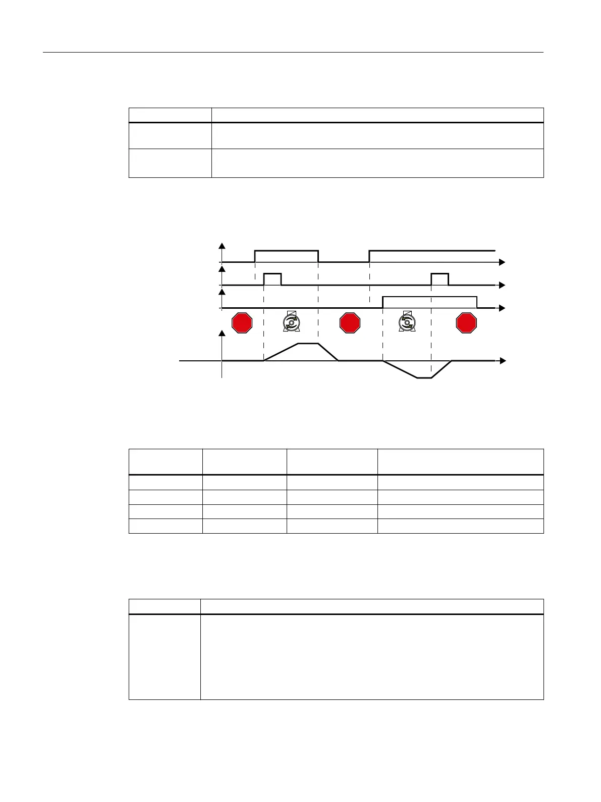
(QDEOH2))
6SHHGVHWSRLQW
The "Enable" command is a precondition for switching on the motor. Commands "ON
clockwise rotation" and "ON counter-clockwise rotation" switch on the motor - and
simultaneously select a direction of rotation. Removing the enable switches the motor o
(OFF1).
Enable / OFF1 ON clockwise ro‐
tation
ON counter-clock‐
wise rotation
Function
0 0 or 1 0 or 1 OFF1: The motor stops.
1 0→1 0 ON: Clockwise motor rotation.
1 0 0→1 ON: Counter-clockwise motor rotation.
1 1 1 OFF1: The motor stops.
Parameters
Select three-wire control, method1
Parameter Description
p0015=63 Macro drive unit
You must carry out quick commissioning in order to set parameter p0015.
Assigning digital inputs DI to the commands:
DI0: Enable/OFF1
DI1: ON counter-clockwise rotation
DI 2: ON clockwise rotation
Advanced commissioning
7.4Controlling clockwise and counter-clockwise rotation via digital inputs
SINAMICS G115D Wall Mounted distributed drive
140 Operating Instructions, 07/2023, FW V4.7 SP14, A5E52808211A AA
 Loading...


