12.3.17 Hollow shaft with splines
* Not included in scope of supply
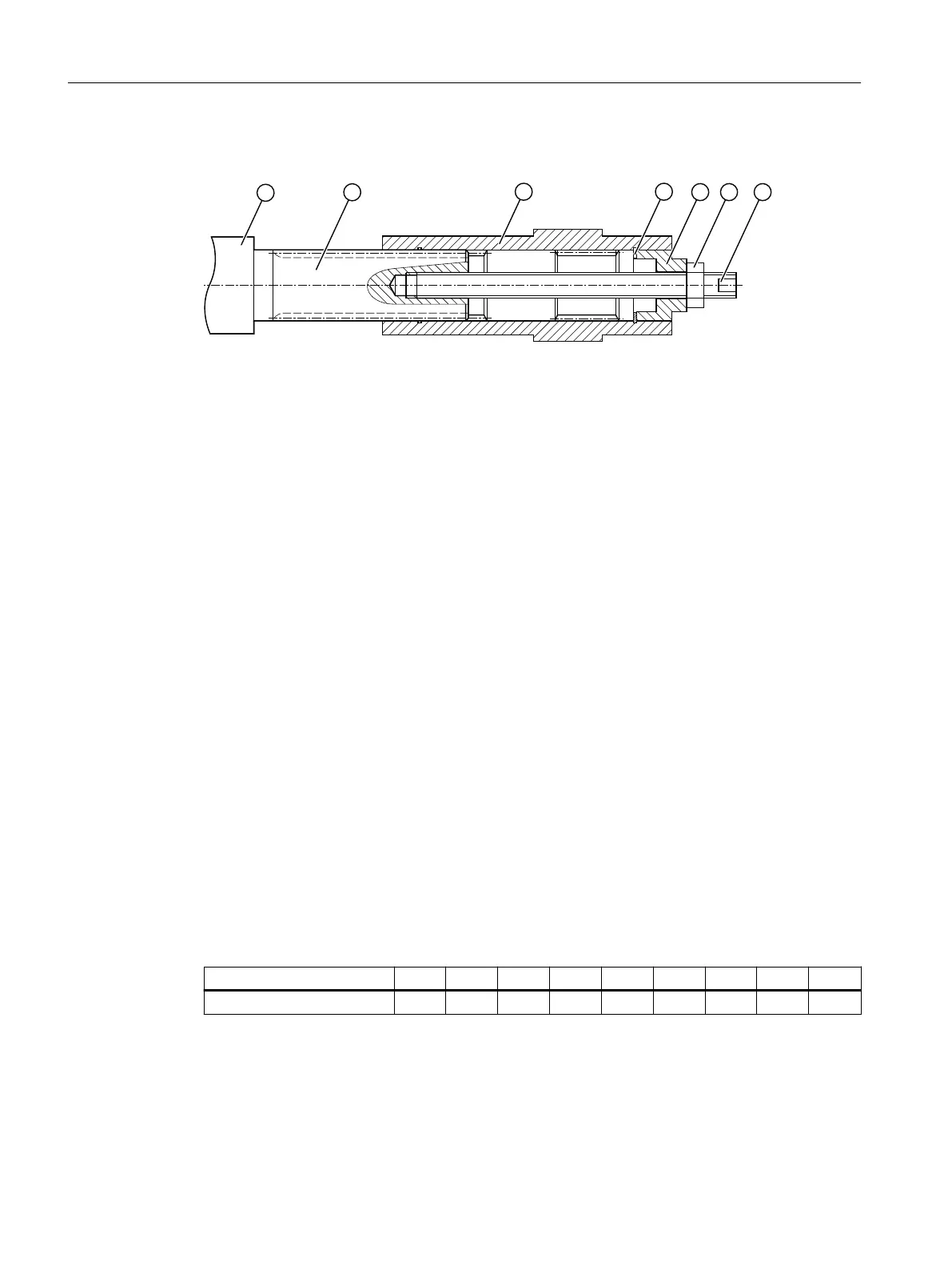
① Machine shaft
② Hollow shaft
③ Hexagon nut
④ Threaded spindle
⑤ Disk
⑥ Locking ring
⑦ Mounting paste
Figure12-25 Mounting the hollow shaft with splines
Instead of the nut and threaded spindle shown in the diagram, other types of equipment
such as hydraulic lifting equipment may be used.
Procedure
1. Using benzine or a solvent, remove the anti-corrosion protection from the shaft ends and
anges.
2. Check the seats or edges of the hollow and machine shafts for any damage. Contact
Technical Support if you notice any damage.
3. Apply the mounting paste⑦ to the machine shaft①. Apply the paste uniformly.
4. Fit the gearbox using the disk ⑤, threaded spindle ④ and nut ③. Support is provided by the
hollow shaft②.
5. Replace the nut③ and the threaded spindle④ with a screw. Tighten the bolts to the
specied torque.
You have mounted the hollow shaft with splined shaft.
Table 12-39 Tightening torque for the screw
Thread size M5 M6 M8 M10 M12 M16 M20 M24 M30
Tightening torque in Nm 5 8 8 14 24 60 120 200 400
Additional information on the SIMOGEAR geared motor
12.3Specic data gearbox
SINAMICS G115D Wall Mounted distributed drive
504 Operating Instructions, 07/2023, FW V4.7 SP14, A5E52808211A AA
 Loading...


