5.14.2 Interface description - X03
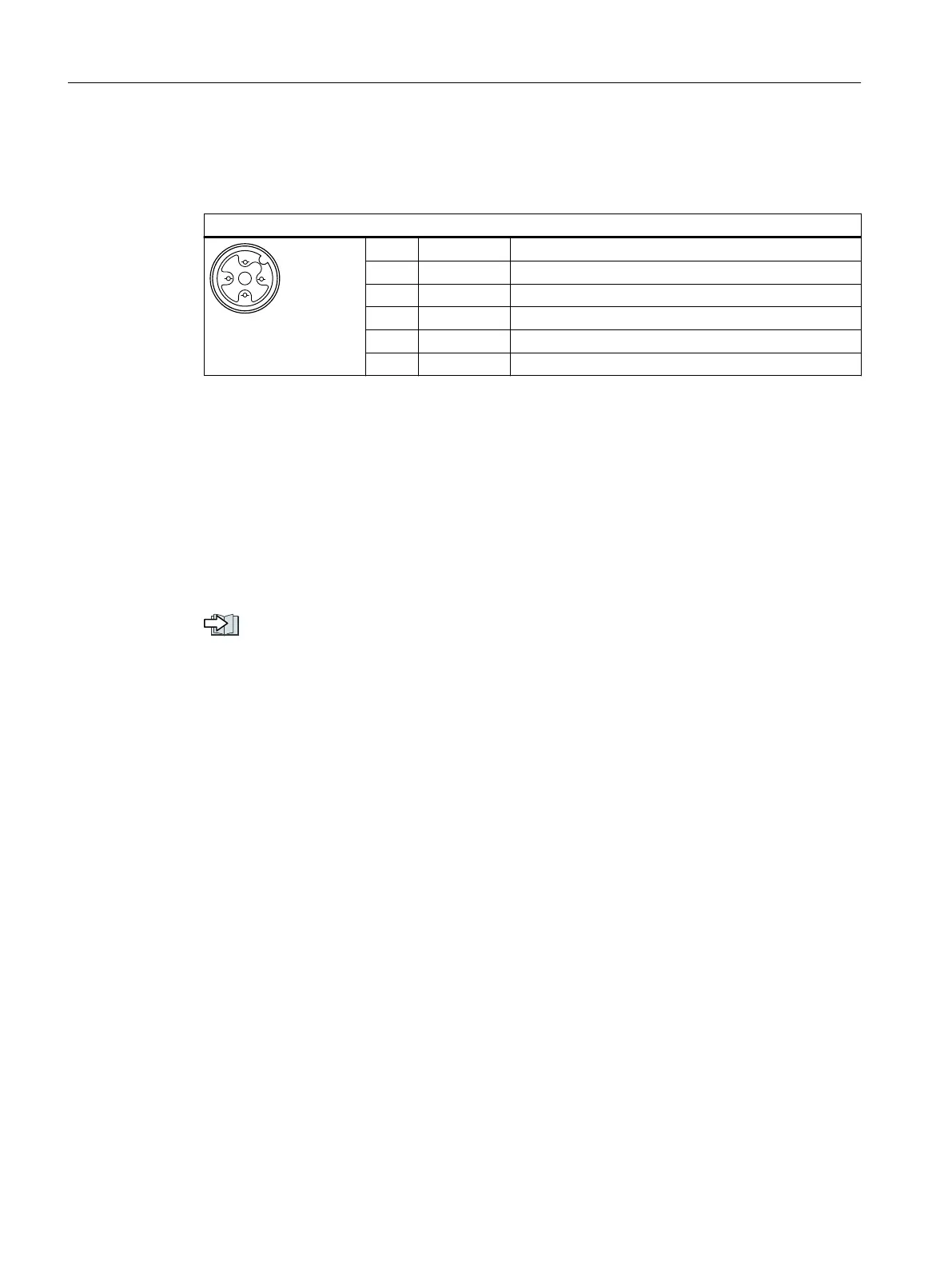
M12 A-coding connector
X03 - AS-i, 5-pin, male
Pin Signal Description
1 AS-i + AS-i positive
2 AUX - Auxiliary 0V
3 AS-i - AS-i negative
4 AUX + Auxiliary 24V
5 FE Not connected
Requirements for applications in USA and Canada
Use a NEC Class2 or a limited voltage/limited current power supply as an external 24V DC
voltage source.
Further information
A number of converters can be connected via the same AS-i cable to the 24 V power supply with
a total current of up to 8 A. Further connection information can be found in the AS-Interface
system manual.
Overview of the manuals (Page588)
5.14.3 Setting the address
As factory setting, all AS-i slaves have address 0. Slaves with address 0 are not included in the
communication.
The addresses must be unique, although they can be mixed as required.
You have the following options when making the address assignment:
• Automatic addressing via the AS-i master
• Addressing via the addressing device
• Addressing via parameters
Before you set the address, you must specify whether the converter is integrated as Single
Slave or Dual Slave in the AS-i network.
• p2013= 0: Single Slave (factory setting)
• p2013= 2: Dual Slave
Wiring
5.14Connecting to AS-i
SINAMICS G115D Wall Mounted distributed drive
96 Operating Instructions, 07/2023, FW V4.7 SP14, A5E52808211A AA
 Loading...


