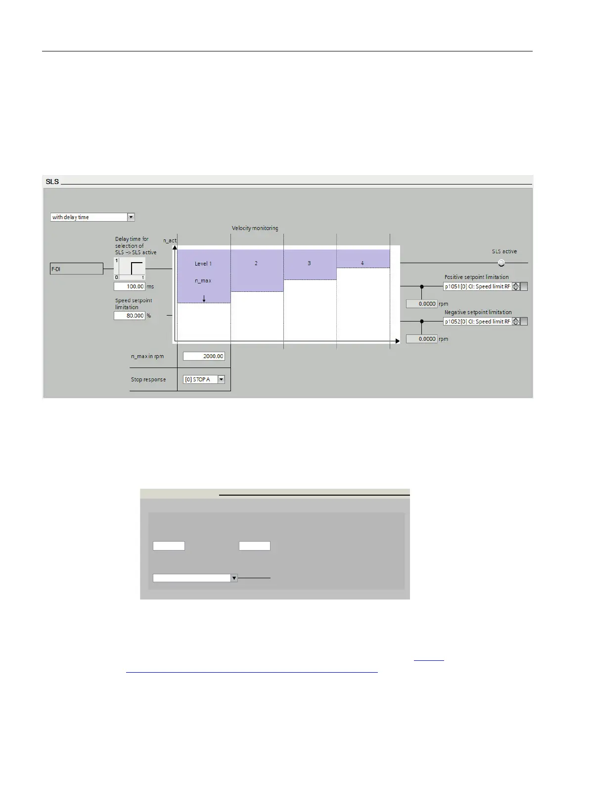
5. Set the SLS speed limit.
With the setpoint limitation the converter limits the speed setpoint when SLS is selected.
If this function is required, the signal interconnection must be set after upgrading from V4.7
SP13 to V4.7 SP14:
– p9733[0] = p1051[0]
– p9733[1] = p1052[0]
Figure7-7 Setting the SLS limits
6. Select "Test stop".
→ Set the monitoring time to a value to match the application.
7. Select "F-DI / F-DO/ PROFIsafe"
→ Set the F-DI conguration.
→ Select F-DI if you want to acknowledge the safety alarms without using STO (see Step 3).
'%*'%0130'*TBGF
'%*DPOHVSBUJPO
'%*EJTDSFQBODZUJNF
<>TUBUJDBMMZBDUJWF
'%*TFMFDUJPO
"DLOPXMFEHFNFOUPG4BGFUZ*OUFHSBUFEBMBSNT
'%*JOQVUMUFS
NTNT
Figure7-8 F-DI / F-DO/ PROFIsafe conguration
8. Finalize the commissioning.
For futher details, please refer to the Safety Integrated Function Manual,
available at the following link: Safety Integrated Function Manual (https://
support.industry.siemens.com/cs/ww/en/view/109782490)
Advanced commissioning
7.16Safely Limited Speed (SLS)
SINAMICS G115D Wall Mounted distributed drive
254 Operating Instructions, 07/2023, FW V4.7 SP14, A5E52808211A AA
 Loading...


