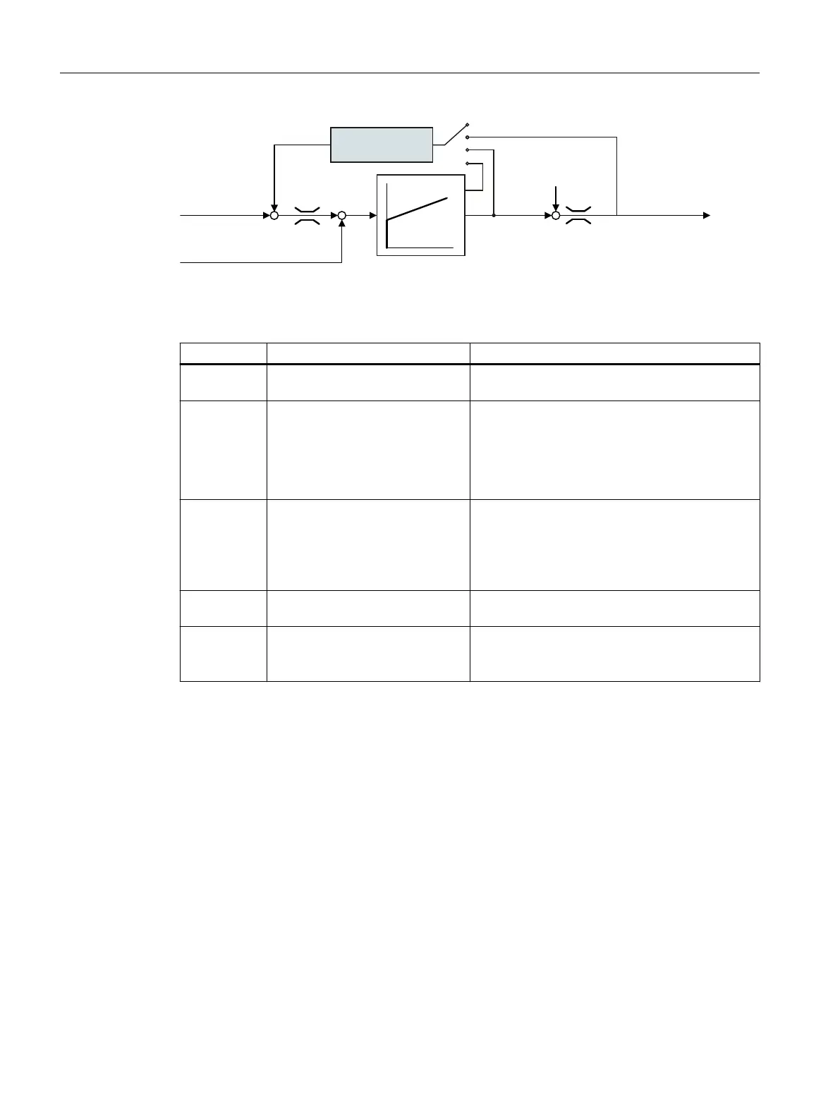
6HWSRLQWIURP
UDPSIXQFWLRQ
JHQHUDWRU
7RUTXHVHWSRLQW
6SHHGFRQWUROOHU
7RUTXHSUHFRQWURO
'URRS
6SHHGDFWXDOYDOXH
.
3
7
,
When droop is active, the ramp-function generators of all of the coupled drives must be set
to have identical ramp-up and ramp-down times as well as rounding-o.
Parameter Description Setting
r1482 CO: Speed controller I torque out‐
put [Nm]
Display and connector output for the torque set‐
point at the output of the I speed controller.
p1488[0...n] Droop input source
Sets the source for droop feedback.
0: Droop feedback not connected (factory setting)
1: Droop from the torque setpoint
2: Droop from the speed control output
3: Droop from the integral output, speed controller
p1489[0...n] Droop feedback scaling Sets the scaling for the droop feedback
A value of 0.05 means: At the rated motor torque,
the converter reduces the speed by 5% of the rated
motor speed.
Factory setting: 0.05
r1490 CO: Droop feedback speed reduc‐
tion [rpm]
Displays the output signal of the droop calculation.
p1492[0...n] BI: Droop feedback enable Enables the droop to be applied to the speed/veloc‐
ity setpoint.
Factory setting: 0
You can nd additional information in the List Manual, function block diagram 6030.
Special settings for a pulling load
For a pulling load, e.g. a hoisting gear, a permanent force is exerted on the motor, even when
the motor is stationary.
Advanced commissioning
7.20Motor control
SINAMICS G115D Wall Mounted distributed drive
294 Operating Instructions, 07/2023, FW V4.7 SP14, A5E52808211A AA

 Loading...


