Binectors and connectors
Connectors and binectors are used to exchange signals between the individual blocks:
• Connectors are used to interconnect "analog" signals (e.g. MOP output speed)
• Binectors are used to interconnect digital signals (e.g. "Enable MOP up" command)
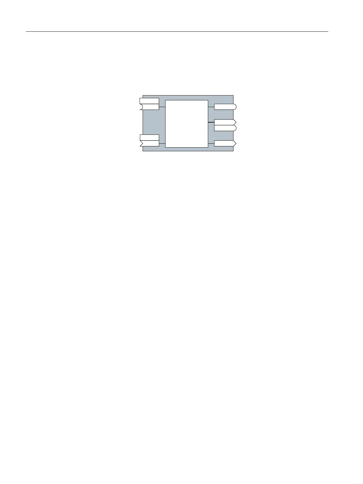
%,&2EORFN
%LQHFWRULQSXW
%LQHFWRURXWSXW
%LQHFWRUFRQQHFWRURXWSXW
&RQQHFWRURXWSXW
&RQQHFWRULQSXW
S[[[[
U[[[[
U[[[[
U[[[[
U[[[[
S[[[[
%,
&2
%2
&2%2
&,
Binector/connector outputs (CO/BO) are parameters that combine more than one binector
output in a single word (e.g. r0052 CO/BO: status word 1). Each bit in the word represents
a digital (binary) signal. This summary reduces the number of parameters and simplies
parameter assignment.
Binector or connector outputs (CO, BO or CO/BO) can be used more than once.
Interconnecting signals
When must you interconnect signals in the converter?
If you change the signal interconnection in the converter, you can adapt the converter to
a wide range of requirements. This does not necessarily have to involve highly complex
functions.
Example 1: Assign a dierent function to a digital input.
Example 2: Switch the speed setpoint from the xed speed to the analog input.
Principle when connecting BICO blocks using BICO technology
When interconnecting the signal, the following principle applies: Where does the signal
come from?
An interconnection between two BICO blocks consists of a connector or a binector and a BICO
parameter. The input of a block must be assigned the output of a dierent block: In the BICO
parameters, enter the parameter numbers of the connector/binector that should supply its
output signal to the BICO parameter.
How much care is required when you change the signal interconnection?
Note which changes you make. A subsequent analysis of the set signal interconnections is
possible only by evaluating the parameter list.
Where can you nd additional information?
• All the binectors and connectors are located in the parameter list in the List Manual.
• The function diagrams in the List Manual provide a complete overview of the factory setting
for the signal interconnections and the setting options.
Appendix
A.1Interconnecting signals in the converter
SINAMICS G115D Wall Mounted distributed drive
582 Operating Instructions, 07/2023, FW V4.7 SP14, A5E52808211A AA

 Loading...


