Wall-mounted converter
'4"
'4#
'4$
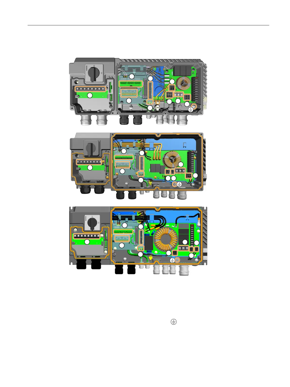
① Line supply terminals - L1, L2, L3, PE ⑥ Motor temperature sensor terminals - T+, T-
② Motor power terminals - U, V, W ⑦ Braking resistor terminals - DCP, PB
③ Digital inputs/outputs terminals - DI0~DI3,
DIO24, DIO25
⑧ 180VDC EM brake terminals - EM+, EM-
④ Switched/unswitched 24 V power supply ter‐
minals - 2L+, 2M / 1L+, 1M
⑨ Optional 400 V AC EM brake terminals - EM1,
EM2 (for G115D Wall Mounted only)
⑤ DIP switches - DIP1, DIP2 Protective earth
Wiring
5.7Overview of the converter interfaces
SINAMICS G115D Wall Mounted distributed drive
Operating Instructions, 07/2023, FW V4.7 SP14, A5E52808211A AA 63

 Loading...


