Programming and Operating Manual (Turning)
01/2017
115
Tool offset number D (turning)
Functionality
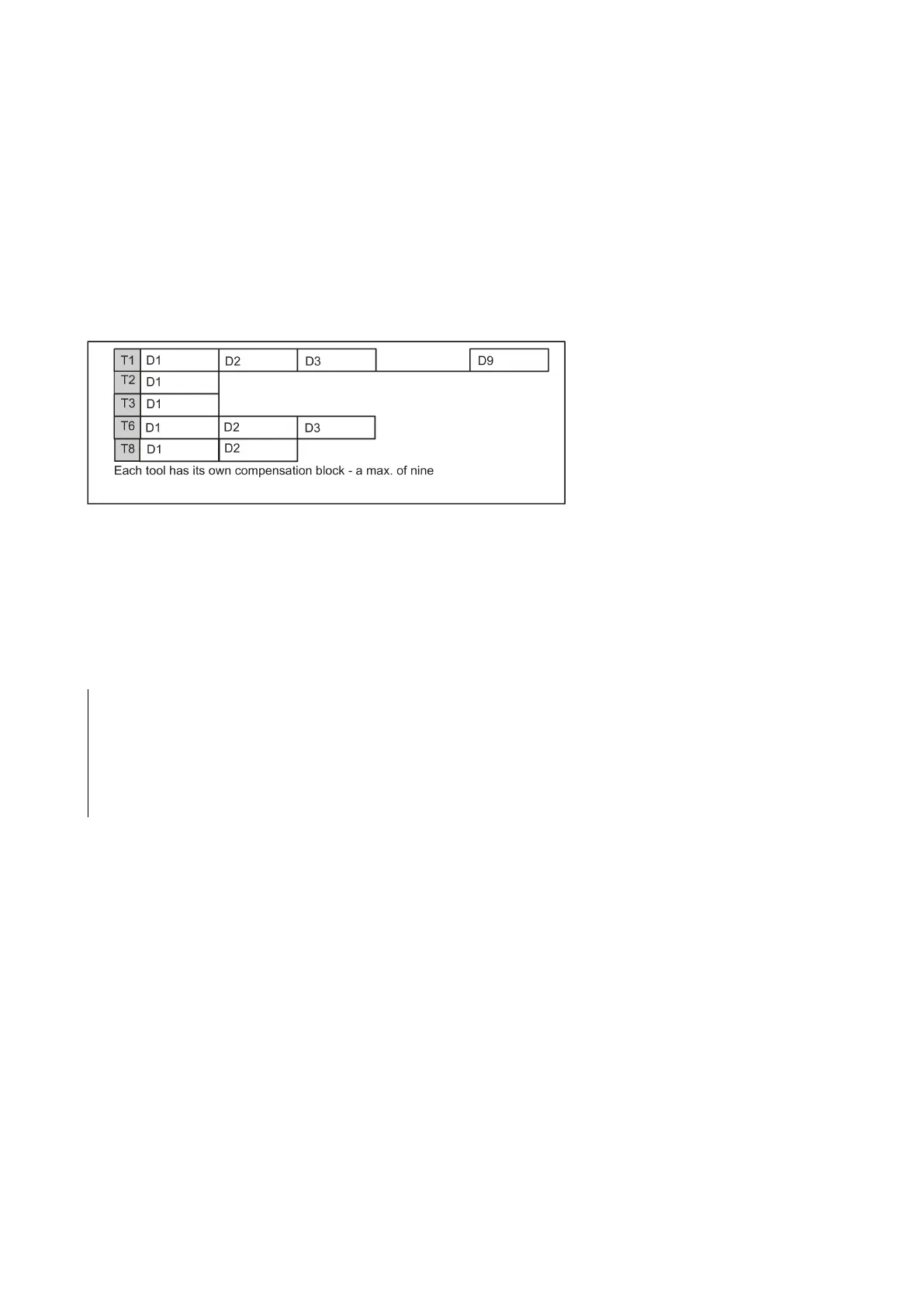
It is possible to assign 1 to 9 data fields with different tool offset blocks (for multiple cutting edges) to a specific tool. If a
special cutting edge is required, then it can be programmed using D and the appropriate number.
If a D word is not written,
effective.
If
is programmed, the offsets for the tool are
.
; Tool offset number: 1 ... 9, D0: No offsets active!
A maximum of 64 data fields (D numbers) for tool offset blocks can be stored in the control system simultaneously:
Information
Tool length compensations
become effective
when the tool is active; when no D number was programmed with
the values of D1.
The compensation is retracted with the first programmed traversing of the associated length compensation axis.
A
must also be activated by G41/G42.
Tool change:
; Tool 1 is activated with the associated D1
; The length offset compensation is overlaid here
; Load tool 4, D2 from T4 is active
; D1 for tool 4 active, only cutting edge changed
Contents of a compensation memory
● Geometrical dimensions: Length, radius.
They consist of several components (geometry, wear). The control system takes into account the components to obtain a
resulting dimension (e.g. overall length 1, total radius). The respective overall dimension becomes active when the offset
memory is activated.
The way in which these values are computed in the axes is determined by the tool type and the current plane G17, G18,
G19.
● Tool type
The tool type (drill or turning tool) determines which geometry data are required and how they will be calculated.
● Cutting edge position
For the "turning tool" tool type, you must also enter the cutting edge position.
 Loading...


