EasyManuals Logo
Home>Siemens>Control Unit>SINUMERIK

Siemens SINUMERIK User Manual

Siemens SINUMERIK
300 pages
To Next Page IconTo Next Page
To Previous Page IconTo Previous Page
Page #228 background imageLoading...
Page #228 background image
Programming and Operating Manual (Turning)
228 01/2017
13.4
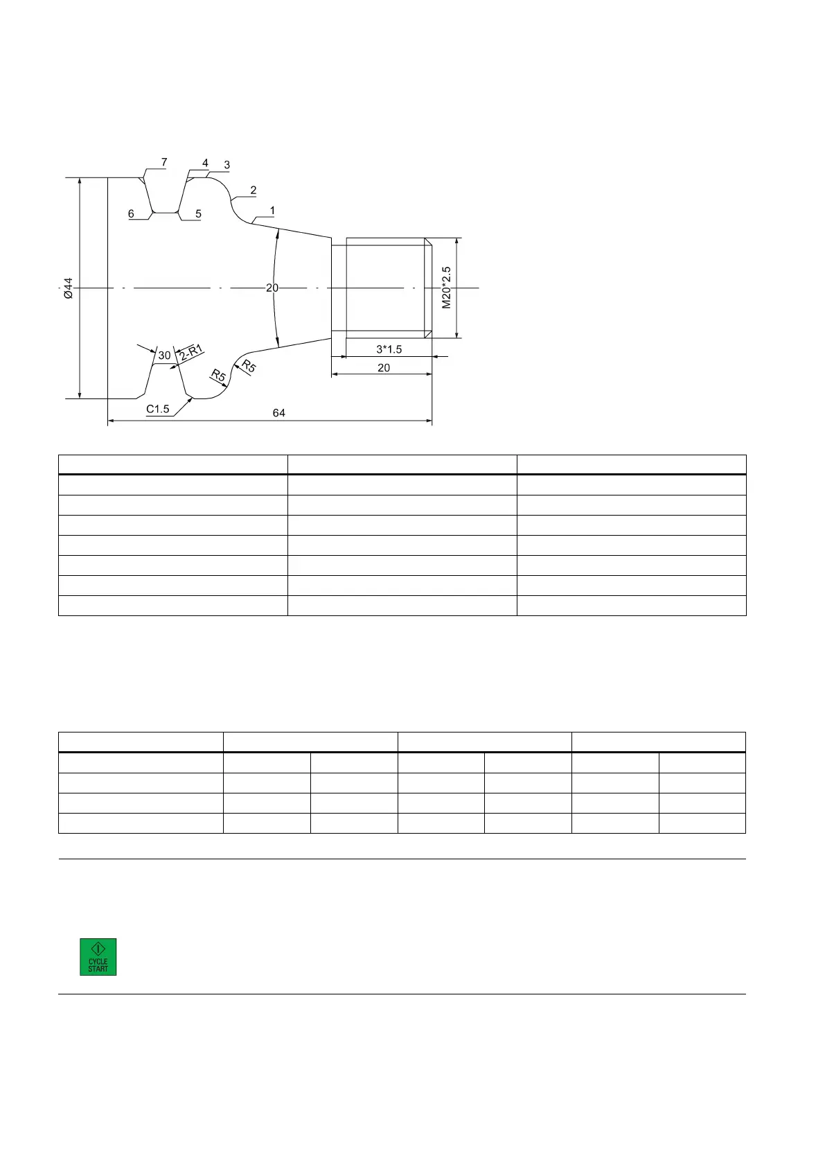
Programming for roughing, grooving and threading (Example 3)
Workpiece drawing (unit: mm)
Coordinates of key machining points
Point
X coordinate
Z coordinate
1 25.596 -35.868
2
34.722
-39.987
3
44.000
-44.974
4
44.000
-48.624
5
30.000
-50.500
6
30.000
-55.500
7
44.000
-57.376
Blank data
Blank material: aluminum bar
Blank diameter: 45 mm
Blank length: 100 mm (machining limit along the Z axis: Z-68; three-jaw chuck clamping length: 25 mm)
Required tools
Tool type
Tool number
Roughing
Finishing
DIN
ISO
Speed
Feedrate
Speed
Feedrate
90 ° roughing tool
T1D1
T0101
S1000
F0.2
S2000
F0.1
3 mm grooving tool
T3D1
T0303
S600
F0.1
S600
F0.05
External threading tool
T4D1
T0404
S600
-
S600
-
Note
•
When programming in ISO mode, you need to set the H numbers of T1, T3, and T4 to 1, 3, and 4 in the tool list
respectively. Three tools are required for the recommended program in ISO mode given later. You need to measure
them before machining. M00 is to stop program execution after cutting is over for each tool. To continue executing the
program, you need to press the following key on the MCP:
• Cut the workpiece manually after machining is over.

Table of Contents

Other manuals for Siemens SINUMERIK

Questions and Answers:

Question and Answer IconNeed help?

Do you have a question about the Siemens SINUMERIK and is the answer not in the manual?

Siemens SINUMERIK Specifications

General IconGeneral
BrandSiemens
ModelSINUMERIK
CategoryControl Unit
LanguageEnglish

Related product manuals