Programming and Operating Manual (Turning)
01/2017
259
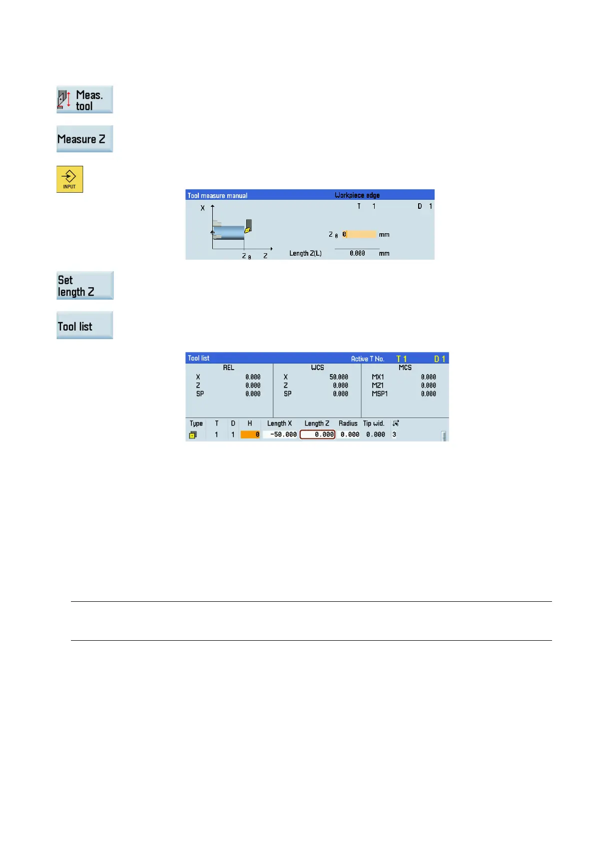
Measuring the Z axis of the tool
Open the manual tool measurement window.
Press this vertical softkey to measure the tool in the Z d
irection.
Enter the distance between the tool
tip and the workpiece edge in the "Z0" field, for exam-
ple, "0". (This value is the thickness of a setting block if it is used.)
Press this softkey and then the system calculates and enters the offset in the geometry
input field of the currently active tool automatically.
Press this softkey and you can see that the compensation data values have been automat
i-
cally added to the tool data.
Repeat the above steps to finish measuring all the tools.
Activating the contour handwheel via the NC program
The contour handwheel function can
help you with the first cutting test after you create a new NC program. When you have
activated this function, you can control the feedrate of path and synchronized axes via a handwheel in "AUTO" or "MDA"
mode. This section only introduces how to activate the contour handwheel via the NC program. For how to activate this
function via the PLC interfaces, see the SINUMERIK 808D/SINUMERIK 808D ADVANCED Function Manual.
● You must not select fixed feedrate, dry-run feedrate, thread cutting, or tapping.
Note
If you have not programmed the feedrate in the previous blocks, the control system prompts an alarm which indicates the
absence of feedrate.
● The axes have been referenced. For more information about how to reference the axes, see Chapter "Switching on and
referencing (Page 18)".
● The option of "Contour handwheel" is activated with a license key. For more information about how to activate an option,
see the SINUMERIK 808D/SINUMERIK 808D ADVANCED Commissioning Manual.
● You have assigned the handwheel to the first geometric axis and activated it. For more information, see Section
"Assigning the handwheel through the MCP (Page 24)".
 Loading...