Programming and Operating Manual (Turning)
278 01/2017
Undercuts for turning technology
Supplementary conditions
The form E and F undercut and form DIN 76 and general thread undercut functions are only activated when the turning
technology is enabled.
Form E and F undercuts as well as thread undercuts are available only if level G18 is set. Undercuts are permitted only on
contour edges of the rotational body, which run in the direction of the longitudinal axis (usually parallel to the Z axis). The
longitudinal axis is identified by the machine data.
The machine data MD 20100 $MC_DIAMETER_AX_DEF for turning machines contains the name of the transverse axis
(usually X). The other axis in G18 is the longitudinal axis (usually Z). If MD 20100 $MC_DIAMETER_AX_DEF does not
contain a name or contains a name that does not conform to G18, there are no undercuts.
Undercuts only appear on corners between horizontal and vertical straight lines, including any straight lines, which are at 0°,
90°, 180° or 270°. A tolerance of ±3° is required here, so that conical threads are also possible (these undercuts do not meet
the standard in this case).
Selecting an undercut form
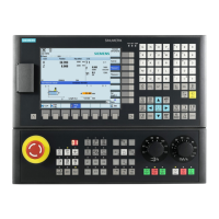
When you choose the transition element in the contour programming window, you can use the following softkey to select an
undercut as a transition element:
You can subsequently define the undercut form by toggling between the selections in the corresponding input fields.
In the case of standard thread undercuts, the characteristic size of the thread pitch is P. The depth, length and transition
radius of the undercut are calculated according to the DIN standard. The (metric) thread pitches specified in DIN 76 can be
used. The entry angle can be freely selected in the 30°-90° range. If the diameter is known when selecting the undercut, an
appropriate thread pitch is suggested. Forms DIN 76 A (external control) and DIN 76 C (internal control) are available. The
program detects the two forms automatically using their geometry and topology.
Based on the thread undercut according to DIN, you can use the general undercut type to create specific undercuts, e.g. for
inch threads.
Specifying contour elements in polar coordinates
Functionality
The description given above of defining the coordinates of contour elements applies to the specification of positional data in
the Cartesian coordinate system. Alternatively, you have the option to define positions using polar coordinates.
When programming contours, you can define a pole at any time prior to using polar coordinates for the first time.
Programmed polar coordinates subsequently refer to this pole. The pole is modal and can be re-defined at any time. It is
always entered in absolute Cartesian coordinates. The contour calculator converts values entered as polar coordinates into
Cartesian coordinates. Positions can be programmed in polar coordinates only
a pole has been specified. The pole
input does not generate a code for the NC program.
The polar coordinates are valid in the level selected with G17 to G19.
The pole is a contour element that can be edited, which itself does not contribute to the contour. It
can be entered when the starting point of the contour is defined or anywhere within the contour. The
pole cannot be created before the starting point of the contour.
 Loading...