Programming and Operating Manual (Turning)
258 01/2017
Additional method for measuring the tool
You must first create a tool (Page 20) and activate it (Page 23) before measuring the tool.
This section takes the turning tool measurement for example. If you have created other types of tools, proceed through
the following steps to finish the measurement of all the tools. This will make the tool change process easier.
Operating sequence
Measuring the X axis of the tool
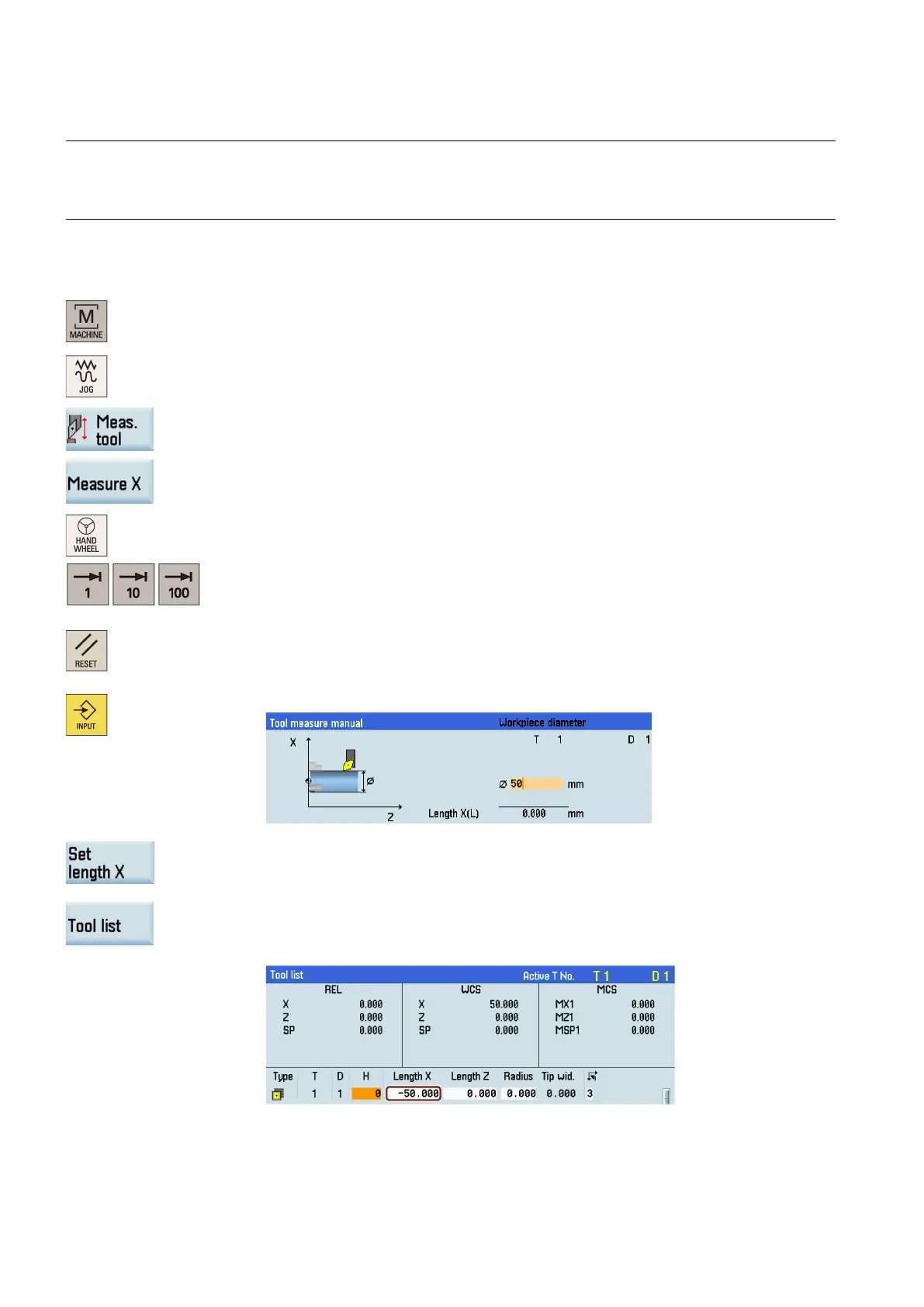
Select the machining operating area.
Open the manual tool measurement window.
Press this vertical softkey to measure the tool in the X direction.
Switch to handwheel control mode.
Select a suitable override feedrate, and use the handwheel to move the tool to cut the su
r-
face of the workpiece for about 1 mm along the X axis and 15 mm along the Z
axis. Then
retract the tool along the Z axis.
Press this key to reset the system. Measure the diameter of the workpiece machined in the
previous step with a calliper.
Enter the workpiece diameter in the "Ø" field (for example, 50).
Press this softkey. The system calculates the offset and enters it in the geometry input field
of the currently active tool automatically.
Press this softkey and you can see that the compensation data values have been automat
i-
cally added to the tool da
ta.
 Loading...