Programming and Operating Manual (Turning)
01/2017
95
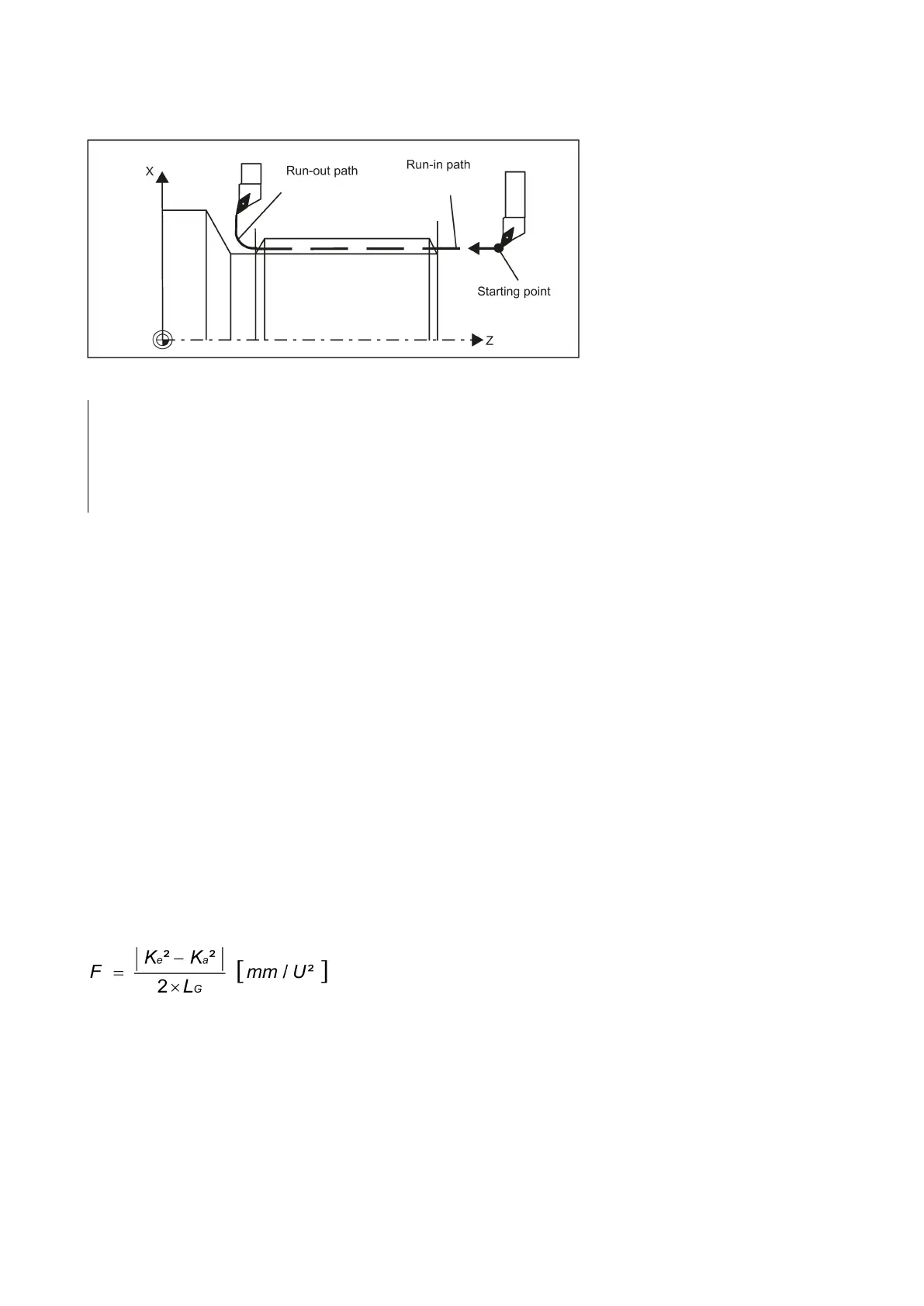
See the following illustration for run-in/run-out path for G33:
N20 G90 G0 Z100 X10 M3 S500
N30 G33 Z50 K5 SF=180 DITS=4 DITE=2
; run-in 4 mm, run-out 2 mm
Thread cutting with variable lead: G34, G35
Functionality
You can produce threads with variable lead in one block with G34 or G35:
● G34 ; Thread with (linearly) increasing lead
● G35 ; Thread with (linearly) decreasing lead
Both functions otherwise have the same functionality as G33 and have the same prerequisites.
G34 or G35 remain active until canceled by another instruction from this G group (G0, G1, G2, G3, G33...).
Thread lead:
● I or K; Starting thread lead in mm/rev., associated with X or Z axis
Lead change:
In the block with G34 or G35, the address F contains the meaning of the lead change:
The lead (mm per revolution) changes per revolution.
Programming: F ; lead change in mm/
rev.
2
.
If you already know the starting and final lead of a thread, you can calculate the thread lead change F to be programmed
according to the following equation:
Explanation:
K
e
Thread lead of the axis end point coordinate [mm/rev]
K
a
Initial thread lead (under I, K progr.) [mm/U]
L
G
Thread length in [mm]
 Loading...


