Programming and Operating Manual (Turning)
01/2017
15
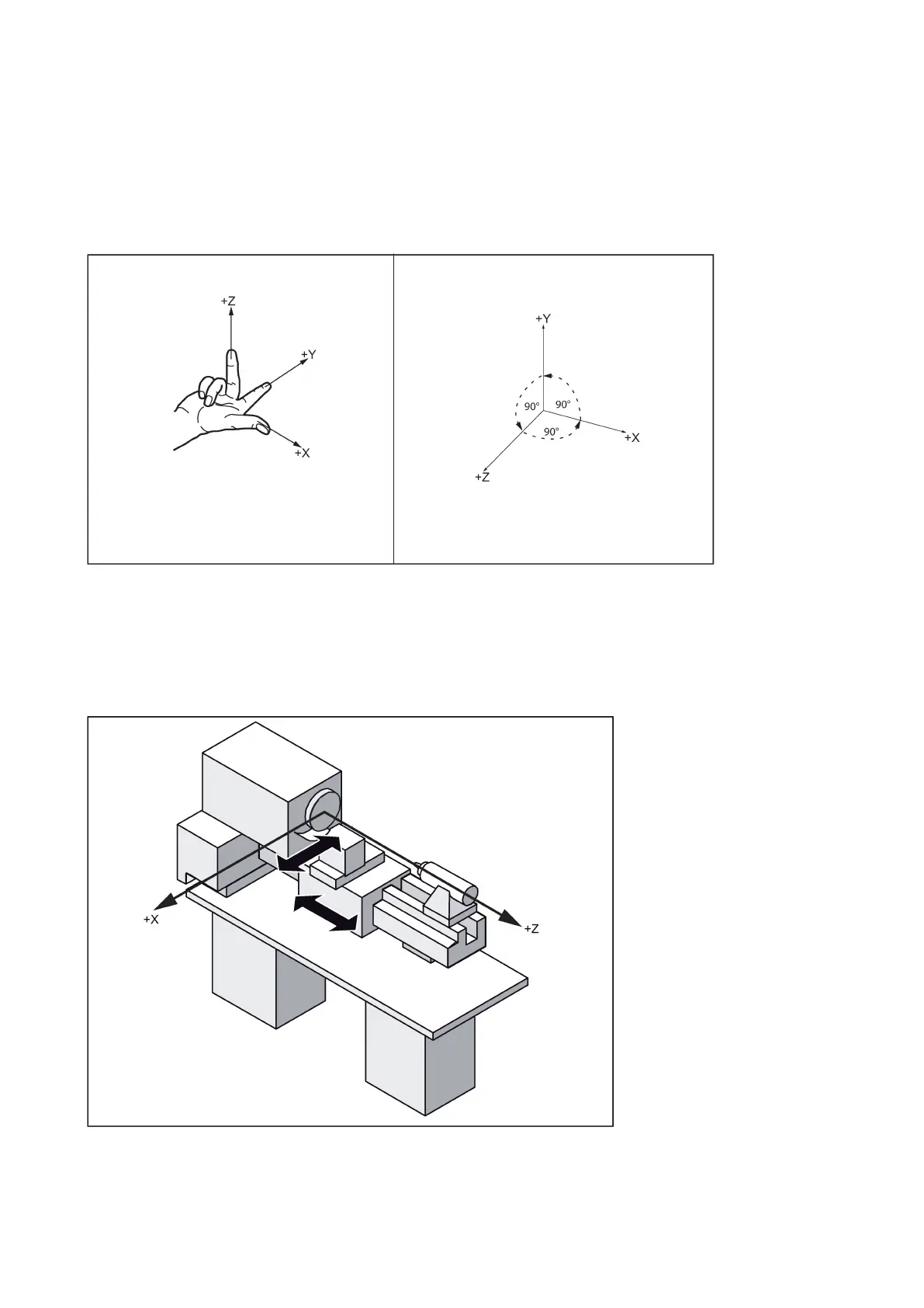
As a rule, a coordinate system is formed from three mutually perpendicular coordinate axes. The positive directions of the
coordinate axes are defined using the Cartesian coordinate system. The coordinate system is related to the workpiece and
programming takes place independently of whether the tool or the workpiece is being traversed. When programming, it is
always assumed that the tool traverses relative to the coordinate system of the workpiece, which is intended to be
stationary.
The figure below illustrates how to determine the axis directions.
Machine coordinate system (MCS)
The orientation of the coordinate system relative to the machine depends on the machine type. It can be rotated in different
positions.
The directions of the axes follow the Cartesian coordinate system. Seen from the front of the machine, the middle finger of
the right hand points in the opposite direction to the infeed of the spindle.
The figure below shows an example of the machine coordinate system of a flat-body turning machine with a front tool holder.
The origin of this coordinate system is the machine zero, defined by the machine manufacturer.
 Loading...