YH4
GRAND
VITARA
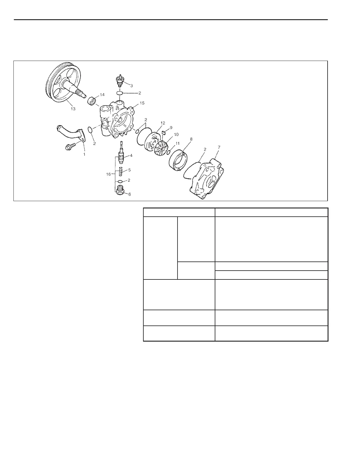
1. Suction connector
2. O-ring
3. Pressure switch
4. Flow control valve
(Relief valve)
5. Spring
6. Plug
7. Pump cover
8. Cam ring
9. Vane
10. Rotor
11. Snap ring
12. Side plate
13. Pulley (pump shaft)
14. Oil seal
15. Pump body
16. Flow control valve Assembly
3B1-4 POWER STEERING (P/S) SYSTEM
POWER STEERING (P/S) PUMP
The power steering pump is a vane type and is driven by the V-ribbed belt from the crankshaft.
Model Vane type
Hydraulic
pressure
control
Relieved
pressure
6500 kPa (65 kg/cm
2
, 924 psi)
G16 Type engine. . . . . . . . . . . . . . . . . . . . . .
7000 kPa (70 kg/cm
2
, 995 psi)
J20 Type engine. . . . . . . . . . . . . . . . . . . . . . .
7350 kPa (73.5 kg/cm
2
, 1045 psi)
H25 Type engine. . . . . . . . . . . . . . . . . . . . . .
Control
Flow control valve
device
Relief valve
Power steering
pressure switch
Switch turns on (closes) when the
pressure is higher than 2500 – 3500 kPa
(25 – 35 kg/cm
2
, 356 – 498 psi).
ECM uses this signal for idle speed control.
Capacity
0.70 – 0.75
(1.48/1.23 – 1.58/1.32 US/Imp. pt)
Specified fluid
DEXRON
II, DEXRON
III A/T fluid
or equivalent
FLOW CONTROL VALVE
As the discharge rate of the P/S pump increases in proportion to the
pump revolution speed, a flow control valve is added to control it so
that the optimum amount of fluid for steering operation is supplied
according to the engine speed (driving condition).
Described below is its operation at different engine speed.
 Loading...