YH4
GRAND
VITARA
“A”
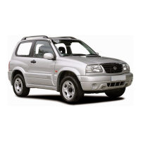
1. Reservoir cap
2. Cylinder
3. Piston assembly
4. Push rod
5. Piston stopper
6. Circlip
7. Boot
8. Lock nut
9. Clevis
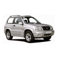
1. Clutch operating cylinder
2. Hose
3. E-ring
7C1-8 CLUTCH
4) Tighten lock nut to specified torque.
Tightening Torque
(a): 10 N
.
m (1.0 kg-m, 7.5 lb-ft)
5) For installation of master cylinder to vehicle, refer to INSTALLA-
TION described previously.
CLUTCH OPERATING CYLINDER
REMOVAL
NOTE:
Do not allow fluid to get on painted surfaces.
1) Clean around reservoir cap and take out fluid with syringe or
such.
2) Disconnect fluid hose from operating cylinder.
3) Remove operating cylinder attaching bolts and operating cylin-
der.
INSTALLATION
1) For air bleeding of master cylinder alone, it must be removed
from vehicle.
For procedures of removal and installation of master cylinder as-
sembly and air bleeding, refer to CLUTCH MASTER CYLINDER
section.
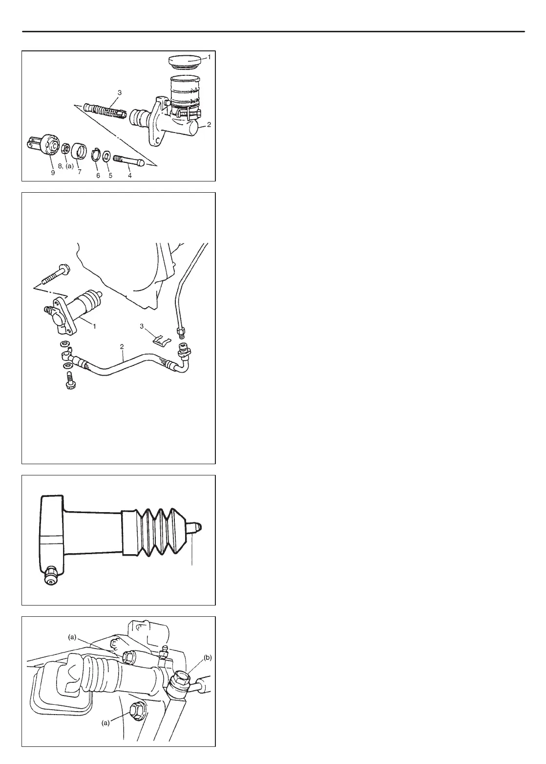
2) Apply small amount of grease to rod tip.
“A”: Grease 99000-25010
NOTE:
Don’t allow any grease to be on boot.
3) Install clutch operating cylinder and torque attaching bolts to
specification.
4) Connect clutch fluid hose and torque union bolt to specification.
Tightening Torque
(a): 50 N
.
m (5.0 kg-m, 36.5 lb-ft)
(b): 23 N
.
m (2.3 kg-m, 16.5 lb-ft)
 Loading...