YH4
GRAND
VITARA
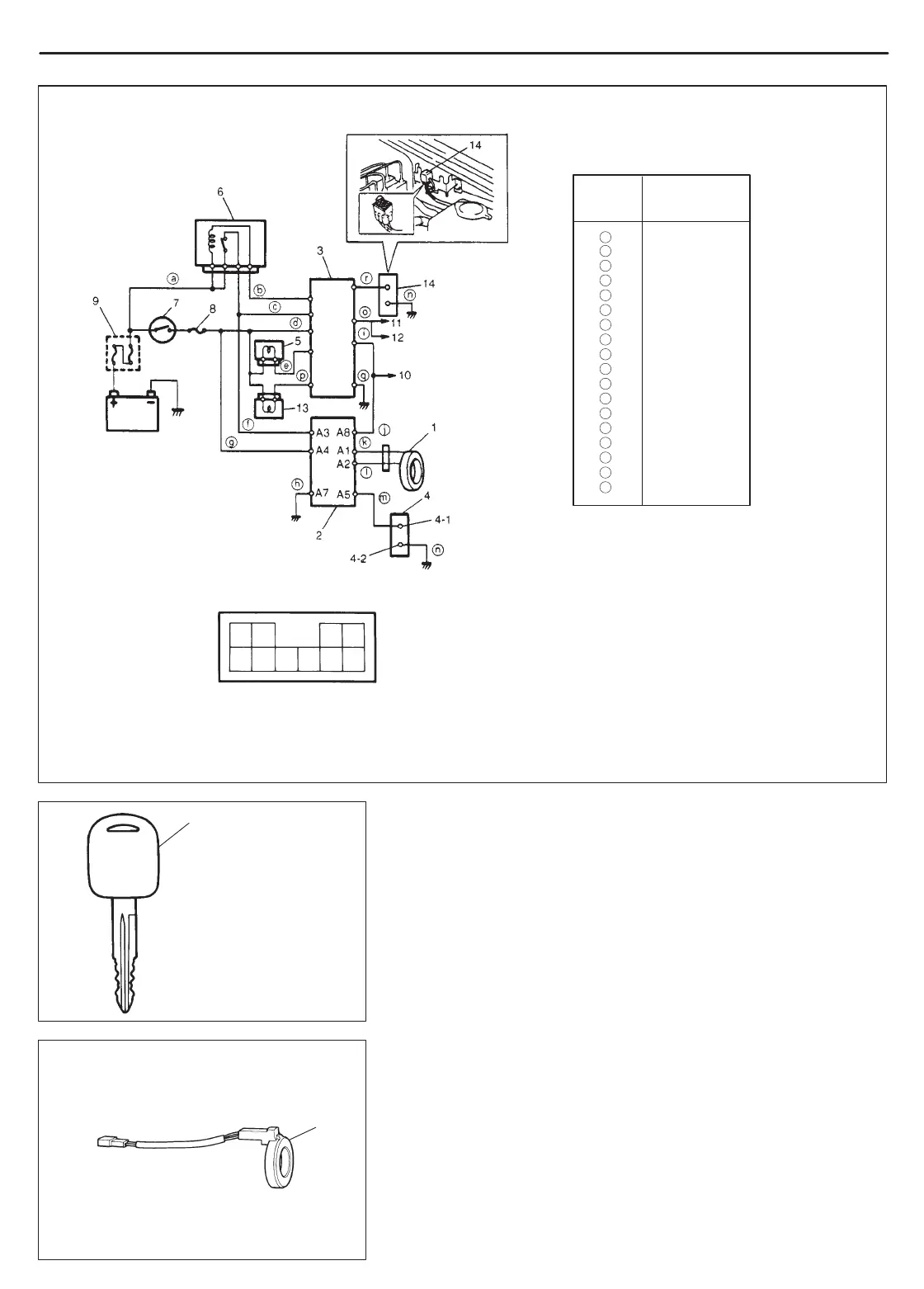
IMMOBILIZER CONTROL SYSTEM (IF EQUIPPED) 8G-3
1
A1 A2 A3 A4
A5 A6 A9 A10A7 A8
1. Coil antenna
2. Immobilizer Control Module
3. ECM/PCM
4. Immobilizer diagnostic coupler
4-1. Diagnostic output terminal
4-2. Ground terminal
5. Malfunction indicator lamp
6. Main relay
7. Ignition switch
8. Fuse
9. Main fuse
-10. To #9-pin in Data link connector
-11. To #7-pin in Data link connector
-12. To ABS control module
-13. Immobilizer indicator lamp
(Vehicle not equipped with monitor coupler)
-14. Monitor coupler (Vehicle not equipped
with immobilizer indicator lamp))
Terminal arrangement of Immobilizer
Control Module coupler (Viewed from
harness side)
B/R
BI
BI/B
B/W
V/Y
BI/B
B/W
B
V/W
V/W
BI
R
SbI
B
V/G
V
B
R/Y
WIRE
SYMBOL
WIRE
COLOR
a
b
c
d
e
f
g
h
i
j
k
l
m
n
1. Ignition key with built-in
transponder
1
1. Coil antenna
o
p
q
r
IGNITION KEY
The ignition key for the immobilizer control system has a built-in
transponder. Each transponder in the key has an each transmitting
code (Transponder code). The code will transmitted from the key
via the coil antenna to Immobilizer Control Module when the ignition
switch is turned ON.
COIL ANTENNA
The coil antenna is installed to the steering lock assembly. As it is
energized by Immobilizer Control Module, it transmits the trans-
ponder code of the ignition key to Immobilizer Control Module.
 Loading...