YH4
GRAND
VITARA
WIRE HARNESS COLOR
B : Black
B/W : Black/White
Bl : Blue
Bl/B : Blue/Black
Bl/R : Blue/Red
Br : Brown
G : Green
Gr : Gray
G/R : Green/Red
Lg : Lightgreen
P : Pink
V : Violet
Y : Yellow
Y/G : Yellow/Green
Y/R : Yellow/Red
W : White
W/B : White/Black
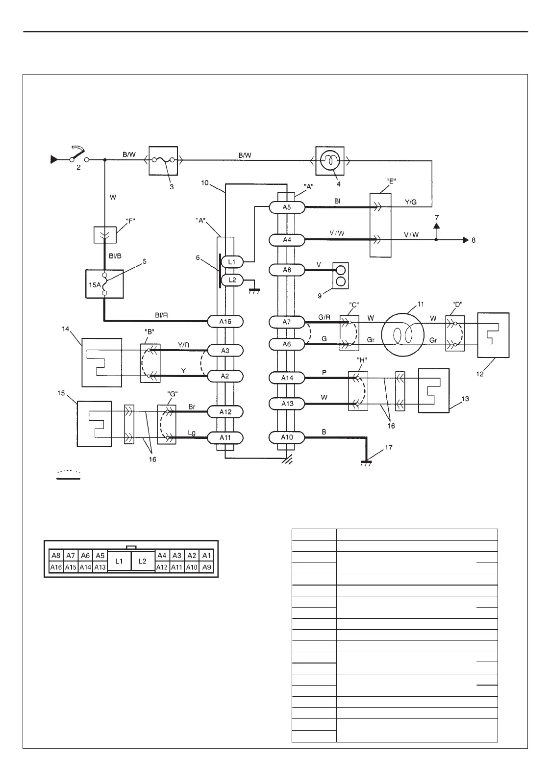
1. From main fuse
2. Ignition switch
3. “IG
.
COIL METER” fuse in J/B
4. “AIR BAG” warning lamp in combination meter
5. “AIR BAG” fuse in “AIR BAG” fuse box
6. Connection detection pin
7. To ECM (or PCM), ICM (if equipped) and ABS
controller (if equipped)
8. To data link connector (DLC)
9. “AIR BAG” monitor coupler
10. SDM
11. Contact coil assembly
12. Driver air bag (inflator) module
13. Driver seat belt pretensioner (if equipped)
14. Passenger air bag (inflator) module
15. Passenger seat belt pretensioner (if equipped)
16. Pretensioner harness (if equipped)
17. Ground for air bag system
TERMINAL
A1
A2
A3
A4
A5
A6
A7
A8
A9
A10
A13
A11
A12
A14
A15
A16
Passenger air bag (inflator) module
Low
High
CIRCUIT
Data link connector (DLC)
Low
High
Low
High
Low
High
“AIR BAG” warning lamp
Driver air bag (inflator) module
Diagnosis switch
–––––––––
Ground
Passenger pretensioner
Driver pretensioner
Ignition switch (power source)
–––––––––
–––––––––
CONNECTOR “A” (SDM connector)
TERMINAL ARRANGEMENT OF SDM
(VIEWED FROM HARNESS SIDE)
L1
L2
Connection detection pin
: Shorting bar
: Air bag harness
“A” “H” : Connector
AIR BAG SYSTEM 10B-5
SYSTEM WIRING DIAGRAM
 Loading...