TURBOCHARGER SYSTEM Turbocharger TC-13
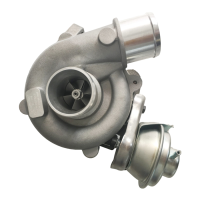
4. INSPECT ACTUATOR OPERATION
(a) Disconnect the actuator hose.
(b) Using SST (turbocharger pressure gauge), apply ap-
prox. 0.92 kg/cm
2
(13.1 psi, 90 kpa) of pressure to the
actuator and check that the rod moves.
SST 09992-00241
If the rod does not move, replace the turbocharger assem-
bly.
NOTICE: Never apply more than 1.05 kg/cm
2
(14.9
psi, 103 kPa) of pressure to the actuator.
INSTALLATION OF TURBOCHARGER
(See page TC-9)
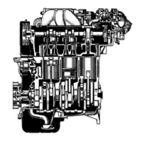
NOTICE: After replacing the turbocharger assembly,
pour approx. 20 cc (1.2 cu in.) of new oil into the oil
inlet and turn the impeller wheel by hand to splash oil
on the bearing.
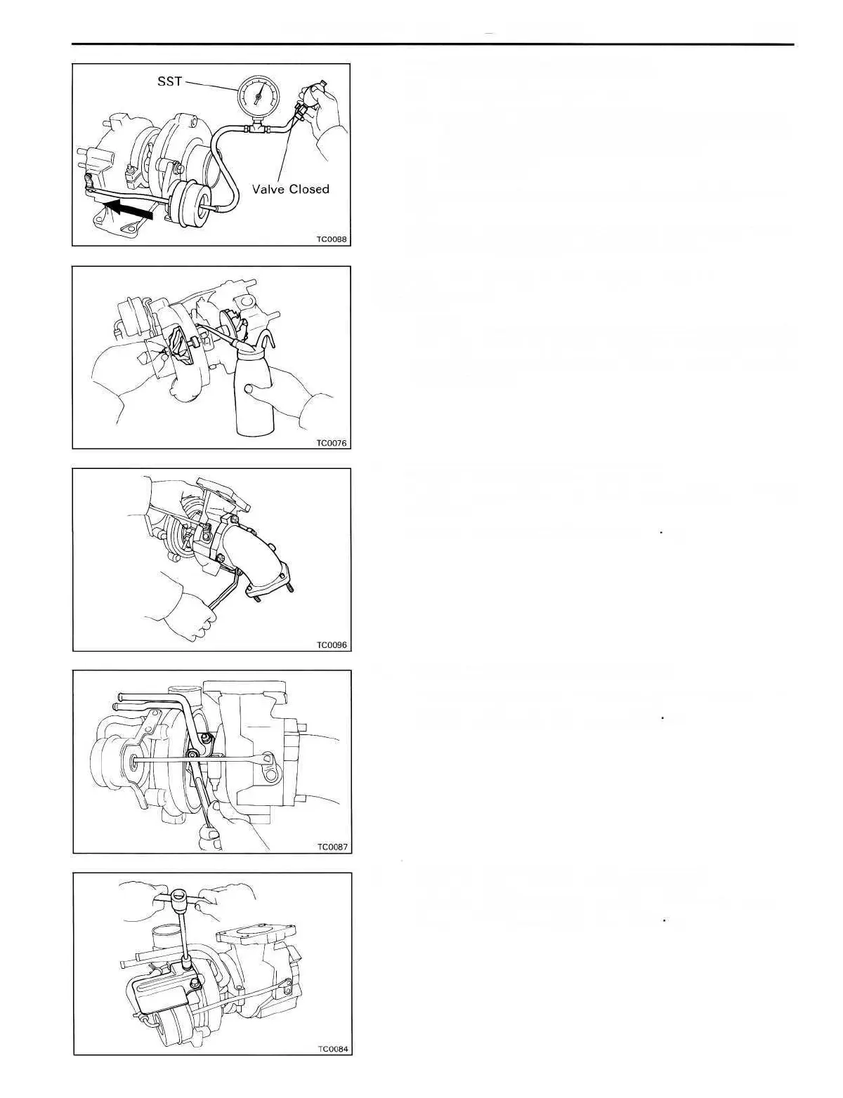
1. INSTALL TURBINE OUTLET ELBOW
Install a new gasket and the turbine outlet elbow with the
four nuts.
Torque: 530 kg-cm (38 ft-lb, 52 Nm)
2. INSTALL NO.1 TURBO WATER PIPE
Install a new gasket and the water pipe with the two nuts.
Torque: 80 kg-cm (69 in.-Ib, 7.8 Nm)
3. INSTALL NO.2 TURBO HEAT INSULATOR
Install the No.2 turbo heat insulator with the two bolts.
Torque: 80 kg-cm (69 in.-Ib, 7.8 Nm)
 Loading...