P
r
o
t
e
c
t
e
d
b
y
c
o
p
y
r
i
g
h
t
.
C
o
p
y
i
n
g
f
o
r
p
r
i
v
a
t
e
o
r
c
o
m
m
e
r
c
i
a
l
p
u
r
p
o
s
e
s
,
i
n
p
a
r
t
o
r
i
n
w
h
o
l
e
,
i
s
n
o
t
p
e
r
m
i
t
t
e
d
u
n
l
e
s
s
a
u
t
h
o
r
i
s
e
d
b
y
V
o
l
k
s
w
a
g
e
n
A
G
.
V
o
l
k
s
w
a
g
e
n
A
G
d
o
e
s
n
o
t
g
u
a
r
a
n
t
e
e
o
r
a
c
c
e
p
t
a
n
y
l
i
a
b
i
l
i
t
y
w
i
t
h
r
e
s
p
e
c
t
t
o
t
h
e
c
o
r
r
e
c
t
n
e
s
s
o
f
i
n
f
o
r
m
a
t
i
o
n
i
n
t
h
i
s
d
o
c
u
m
e
n
t
.
C
o
p
y
r
i
g
h
t
b
y
V
o
l
k
s
w
a
g
e
n
A
G
.
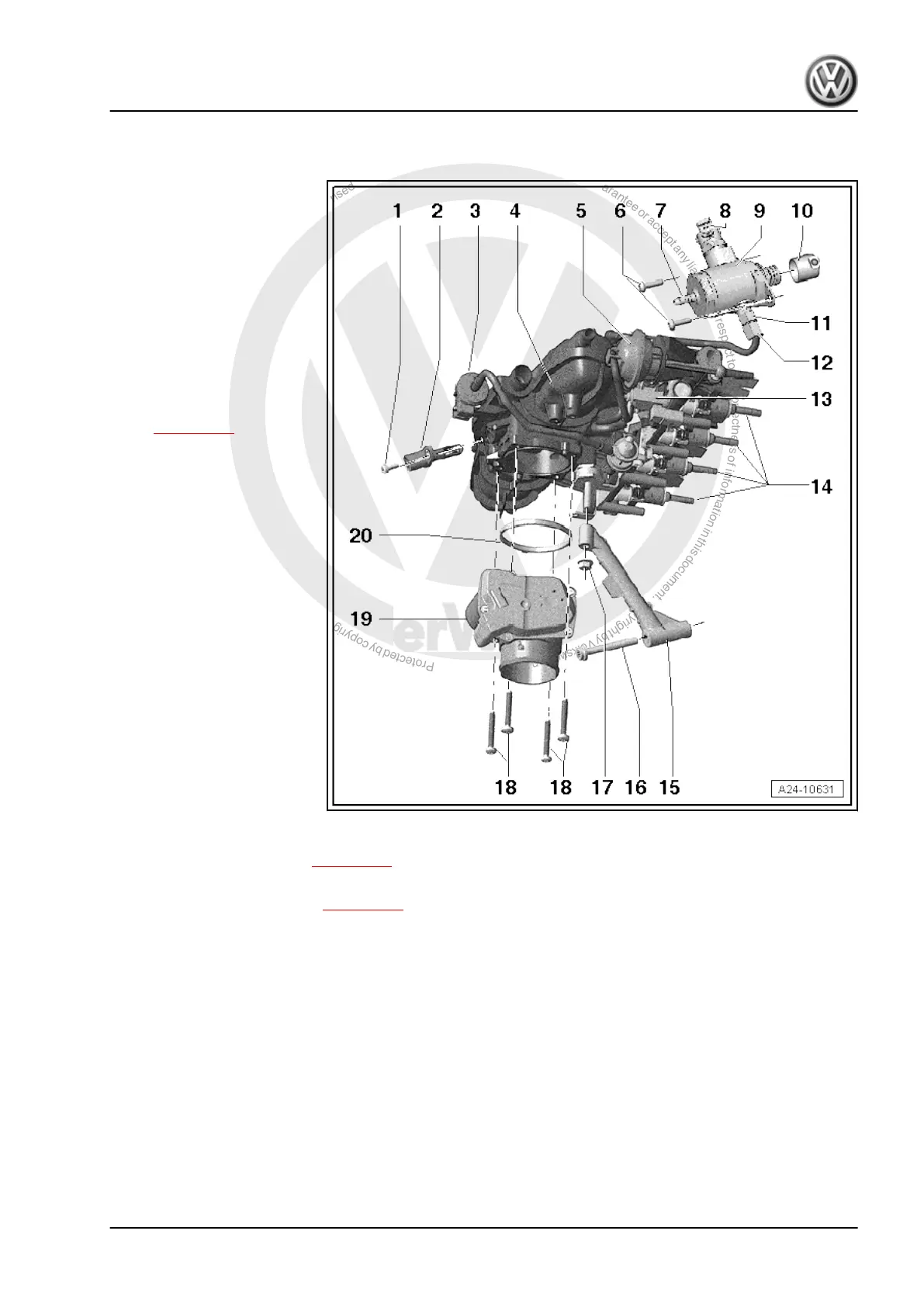
2.6 Assembly overview - intake manifold
1 - Screw for intake air temper‐
ature sender -G42-
❑ 9 Nm
2 - Intake air temperature
sender -G42-
- Activated charcoal filter sole‐
noid valve 1 -N80-
❑ With double non-return
valve, checking ⇒ Vehi‐
cle diagnostic tester.
4 - Intake manifold
❑ Removing and installing
⇒ page 213 .
5 - Vacuum unit for air flow
control flaps (intake manifold
flaps)
6 - Bolts for high-pressure
pump
❑ 20 Nm
7 - Connection for fuel supply
line
❑ From fuel tank
8 - Fuel pressure regulating
valve -N276-
9 - High-pressure pump
❑ With fuel pressure regu‐
lating valve -N276- .
❑ Fuel tank contains elec‐
tric fuel pump which
pumps fuel to mechani‐
cal high-pressure pump.
❑ When installing the
high-pressure pump, it is essential to ensure that no dirt enters the fuel system.
❑ The fuel system must not be under pressure when installing the high-pressure pump; procedure for
reducing fuel pressure ⇒ page 161
❑ Fuel lines must be free of tension when installed.
❑ Removing and installing ⇒ page 226 .
10 - Roller tappet
❑ Can remain inserted in vacuum pump after removal of high-pressure pump, removable
11 - Connection for fuel supply line
❑ Renew.
❑ 40 Nm
12 - High-pressure fuel line
❑ Fuel lines must be free of tension when installed.
❑ 27 Nm
13 - Intake manifold flap air flow control valve -N316-
14 - Injectors
❑ Renew O-ring and Teflon ring
❑ Check installation location is correct
Amarok 2011 ➤
4-cylinder injection engine (2.0 l direct injection engine, turbocharger) - Edition 02.2011
2. Injection system 211

 Loading...