P
r
o
t
e
c
t
e
d
b
y
c
o
p
y
r
i
g
h
t
.
C
o
p
y
i
n
g
f
o
r
p
r
i
v
a
t
e
o
r
c
o
m
m
e
r
c
i
a
l
p
u
r
p
o
s
e
s
,
i
n
p
a
r
t
o
r
i
n
w
h
o
l
e
,
i
s
n
o
t
p
e
r
m
i
t
t
e
d
u
n
l
e
s
s
a
u
t
h
o
r
i
s
e
d
b
y
V
o
l
k
s
w
a
g
e
n
A
G
.
V
o
l
k
s
w
a
g
e
n
A
G
d
o
e
s
n
o
t
g
u
a
r
a
n
t
e
e
o
r
a
c
c
e
p
t
a
n
y
l
i
a
b
i
l
i
t
y
w
i
t
h
r
e
s
p
e
c
t
t
o
t
h
e
c
o
r
r
e
c
t
n
e
s
s
o
f
i
n
f
o
r
m
a
t
i
o
n
i
n
t
h
i
s
d
o
c
u
m
e
n
t
.
C
o
p
y
r
i
g
h
t
b
y
V
o
l
k
s
w
a
g
e
n
A
G
.
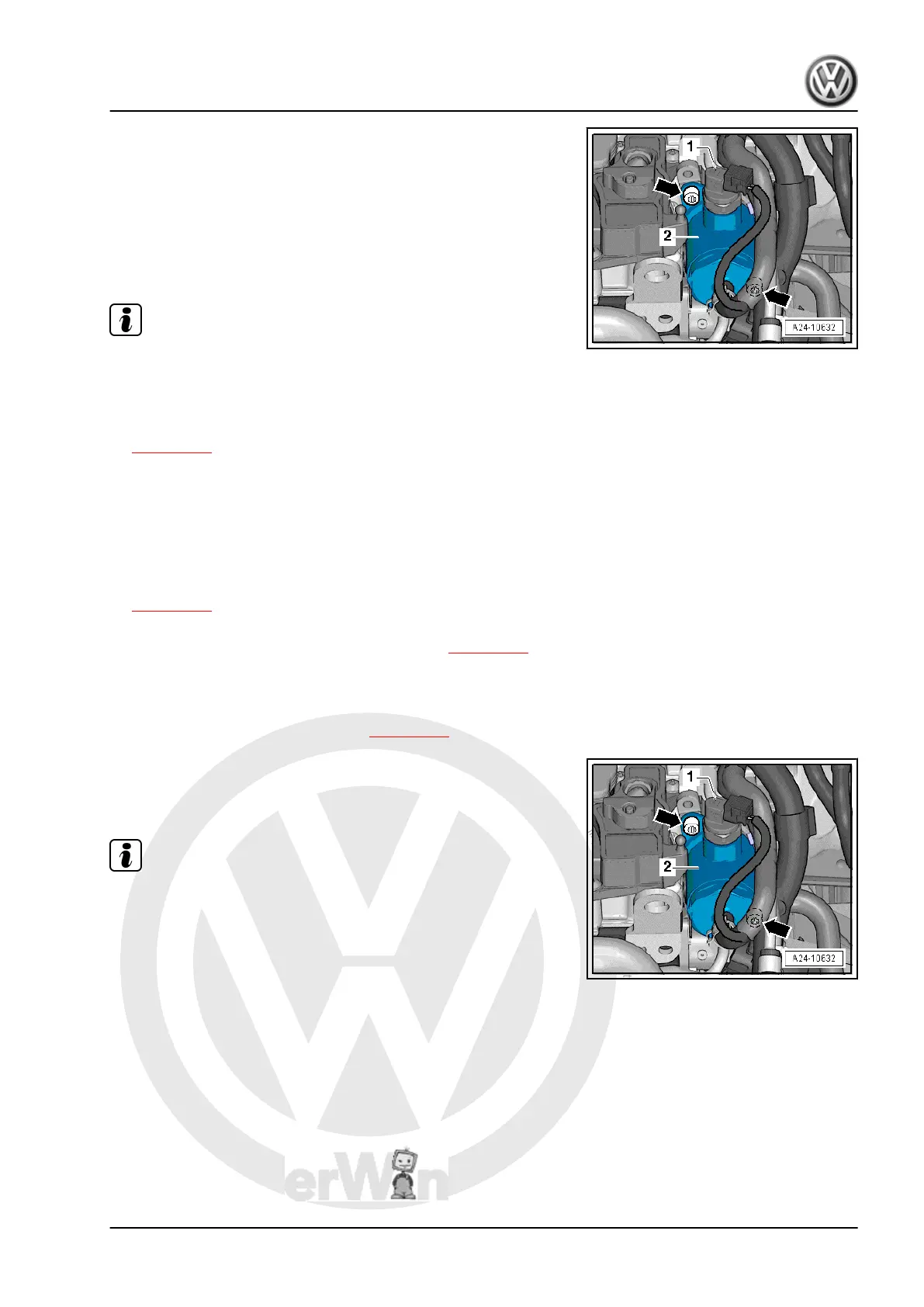
– Remove 2 bolts -arrows-.
– Carefully pull out high-pressure fuel pump. Sleeve can remain
inserted in vacuum pump.
Installing
– Renew high-pressure pump O-ring.
– Insert roller tappet in vacuum pump (first check roller tappet
for damage).
Note
♦
Roller tappet must be at bottom dead centre to enable high-
pressure pump to be installed.
♦
If same or a used high-pressure pump is installed, connection
for fuel pressurisation line (high-pressure side) must be re‐
newed. See assembly overview - high-pressure pump item 11
⇒ page 225
– Turn crankshaft until roller tappet is at bottom dead centre.
– Insert high-pressure pump into vacuum pump and tighten.
– Tighten bolts hand tight.
– Renew high-pressure pump connection.
• Specified torque: assembly overview - high-pressure pump
⇒ page 225 .
– Now tighten bolts in diagonal sequence to specified torque,
see assembly overview - high-pressure pump ⇒ page 225 .
– Tighten union nut of high-pressure line hand-tight. Align free
of tension.
• Specified torque for fuel pressurisation line (union nut): as‐
sembly overview - intake manifold ⇒ page 213 .
– Reattach connector to fuel pressure regulating valve -N276-
-1-.
– Put back fuse if it has been removed.
Note
Check fuel system for leaks.
2.17 Removing and installing engine control
unit
Special tools and workshop equipment required
Amarok 2011 ➤
4-cylinder injection engine (2.0 l direct injection engine, turbocharger) - Edition 02.2011
2. Injection system 227

 Loading...