REPAIR
8--6 27080 Issue 1 Sept 98
but not excessively, to ensure metal--to--metal contact between the
drive rod flange and the gunbody. Refit the drive rod cap.
(8) Pass the drive rod wire through the cable gland (see step (4)) into
the upper part of the head.
(9) Fit a new connector to the drive rod wire and fit a new piece of
heatshrink sleeving onto the drive rod wire.
(10)Connect the drive rod wire into the conduit wiring and use aheat
gun to tighten the sleeving over the connectors.
(11) Refit the cover over the upper part of the head.
Drop Generator Replacement
The printer must be shut down and the print head removed from its
holster.
(1) Remove the cover over the upper part of the head by:
(a) removing the four screws in the sides,
(b) removing the two screws at the top,
(c)carefullypullingthesidesawayfromthechassisandremoving
the cover.
(2) Tracethe wiresfromthedriverod,the headsolenoid valve,heater
and thermal sensor to their connections in the upper part of the
head (see pg. 8--5).
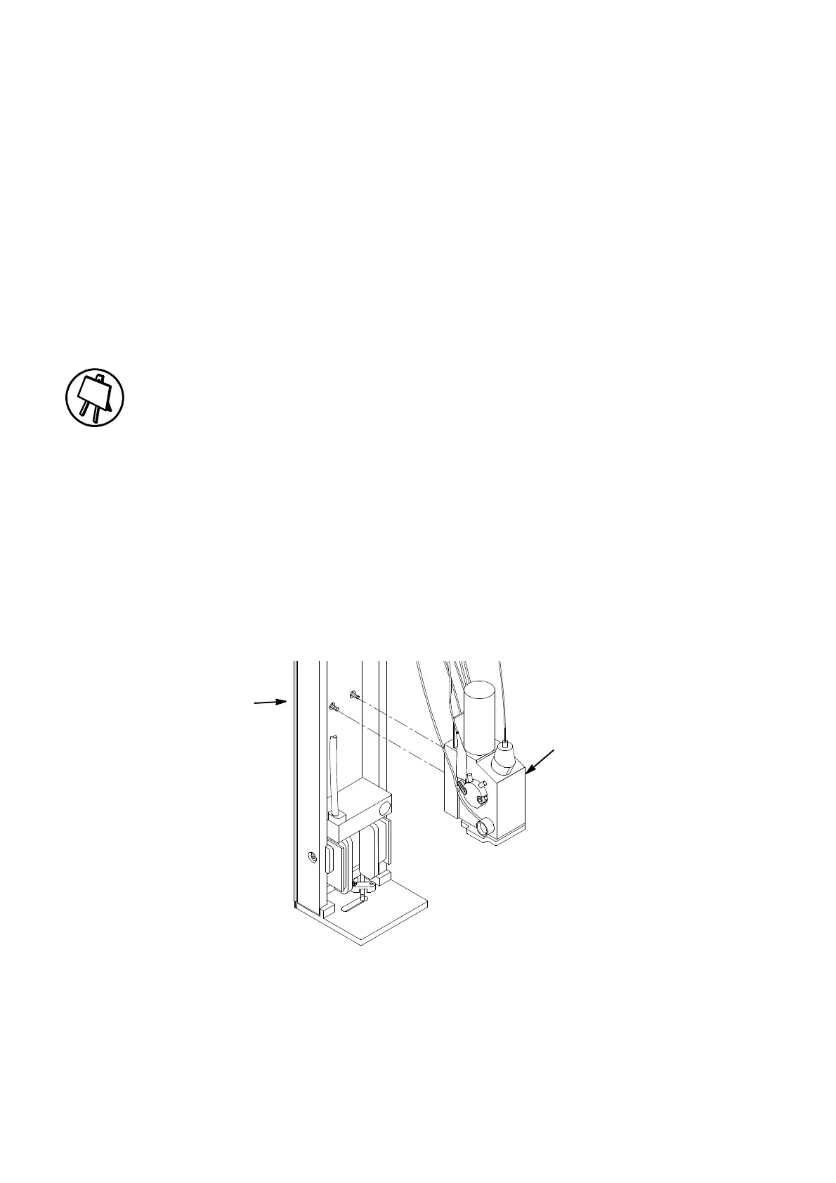
Drop
Generator
Captive Screws
(Rear of Chassis)
Drop Generator Removal
MG060--1
(3) Cuttheheatshrinksleevingaroundtheconnectionsanddisconnect
the wires.
 Loading...


