APPENDIX B : A--SERIES AIR DRIVEN AIRDRYER
20951 Issue 1 Apr 98 B--7
DESCRIPTION
Airdryer --General
The airdryer is housed in a small stainless steel cabinet designed for
either wall mounting, or attachment to the printer stand. Externally,
thecabinet carriesapowerisolator,amainsindicator, a fault lampand
a sounder. Internally, the electronic circuits are carried on a printed
circuit board which is protected by a cover. A special grommet in the
housing wall provides a release for any excess pressure which may
develop in the housing.
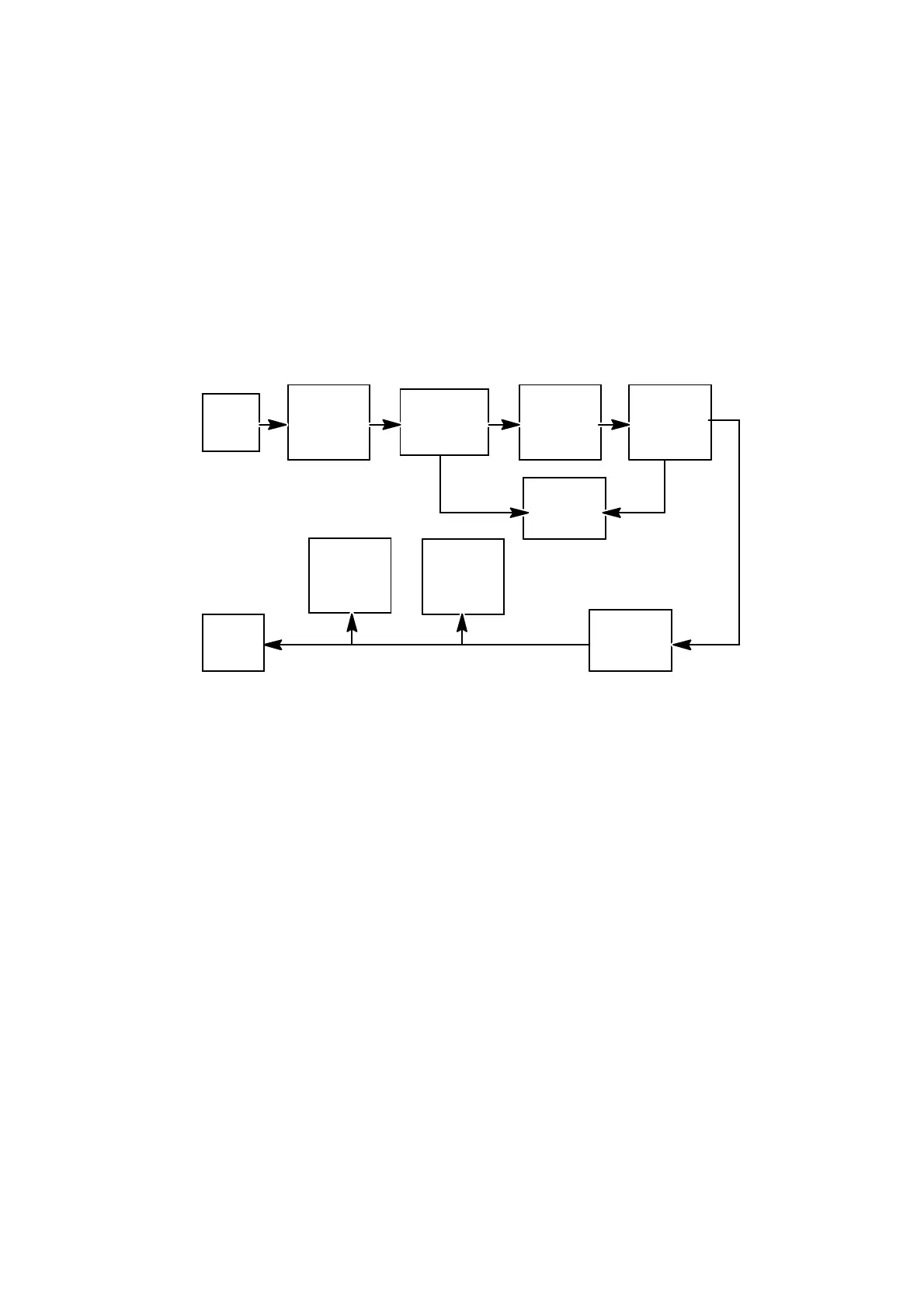
Input
Air
Filter
General
Purpose
Filter
Regulator
Pressure
Detector
Humidity
Sensor
Oil
Removal
Filter
Drain
Vent
Airdryer Schematic Diagram
Output
Restrictor
The airdryer is supplied with factory driven air, that is passed first
through an air filter to remove solid particles and then through a
general purpose constant bleed drain filter, to remove any airborne
condensate (moisture). A regulator reduces the air pressure to a
constant 30psi and the air is passed through a constant bleed drain
coalescingfiltertoremoveanyoil. Finally,anin--linerestrictorreduces
the output airflow to the rate required by the print head.
Ahumiditysensorandapressureswitchareconnectedintothesystem.
If a fault occurs, such as excessive humidity or a drop in pressure, an
external red lamp flashes and an audible alarm is given by a sounder
to warn the operator.
A Printed Circuit Board (PCB) carries a switch that bypasses the
humidityandpressuresensingcircuit(seepg.B--18). Theswitchallows
theunit(a)tobeserviced,or(b)tocontinuetooperateinconditionsthat
areoutsideitsspecification,butwhichareconsideredacceptablebythe
operator. Whilst the switch is in the bypass position, the redindicator
flashes.
 Loading...


