REPAIR
27080 Issue 1 Sept 98 8--21
ELECTRONIC SYSTEM REPAIRS
WARNING: Electrical power to the printer must be
disconnected before opening the electronics
compartment and during any work on the
electronics system.
CAUTIONS (1) Double pole neutral fusing.
(2) Electrostatic discharge precautions must ALWAYS
be taken when entering the electronics compartment
to avoid damage tothecomponents. Aground/earth
chassis connector is provided for connection of a
wrist strap (see diagram below).
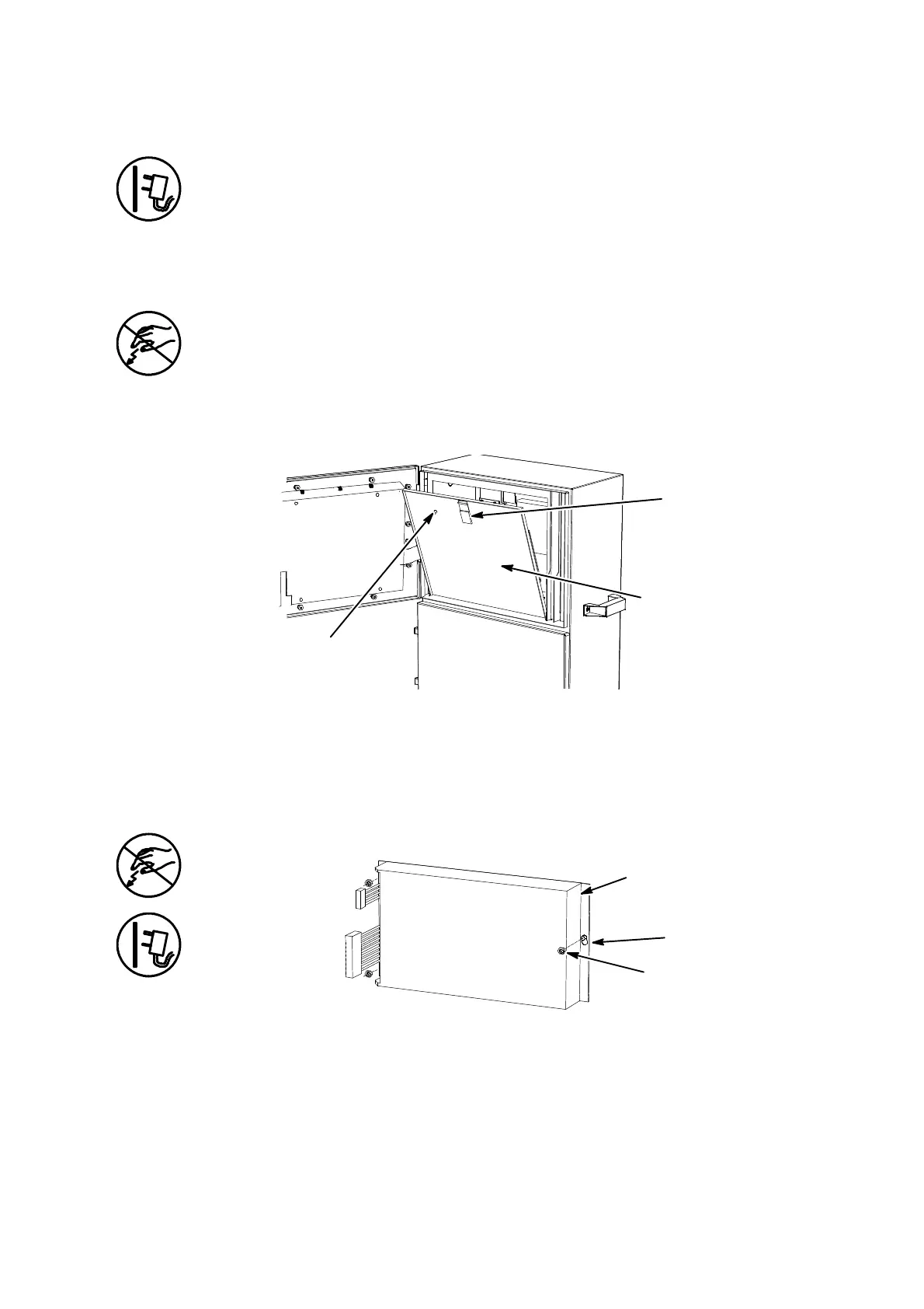
Access
Access -- Electronics Compartment
Electronics
Compartment
Cover
Securing
Latch (or
screw on
A100)
Electrostatic Discharge
Wrist Strap Connector
MG005--2
The front of the electronics compartment is covered by a solid panel
which is released by a latch (or screw on A100) at the top and hinges
down. The Printer Control PCB Assembly and the HV power supply
are mounted on the inside face of the panel.
Power Supply Unit Replacement
Power Supply Unit Replacement
Power Supply
Fixing Nuts
MG007--2
Slotted Hole
The electronics compartment must be open.
(1) Pull off the power supply input and output connections from the
External Interface PCB and the Control PCB Assembly.
(2) Slacken thesecuring screws,slide andliftawaythe power supply.
 Loading...


