APPENDIX A : INSTALLATION
27080 Issue 1 Sept 98 A--15
PRINTER INSTALLATION
Thefollowingisgeneralinformationforinstallingtheprinterinawide
range of working areas.
Printer cabinet and printhead installation dimensions are given in the
diagrams opposite and on pg.A--16. Further details are given on pg.
2--6.
Cabinet Positioning
Thecabinetshouldbeinapositionwherethereisaccesstothefrontand
leftsidewithclearancestoopenthedoorsasgiveninthediagram. The
cabinet must be level and electrically isolated from other equipment,
except for a normal data interface.
For total stability, the cabinet should be mounted on a stand or fitted
with a stabiliser kit (see Part 10 : Options).
Theprinter shouldnotbeputinto an area wherethe temperatureswill
go outside the range +5
o
C and +45
o
C and the relative humidity will
go outside the range 10% to 90% (non--condensing). The A300 printer
draws in and expels cooling air through the underside of the cabinet,
whilst the A200 and A100 printers drawcooling airthrough theupper
right hand side of the cabinet, and expels it through the underside of
the cabinet. Nothingmustbe allowedto interfere with thismovement
of air.
Conduit and Print Head Positioning
The conduit must be kept away from power supply cables and other
wiring capable of producingelectrical noise. The print head must also
be electrically isolated. This is normally achieved by the insulation
coating on the print head and its mounting components. However, if
thereisany dangerofthis beinginsufficient, use the glass--filled nylon
mounting bracket supplied loose with the printer. The print headand
conduit must also be as free as possible from vibration.
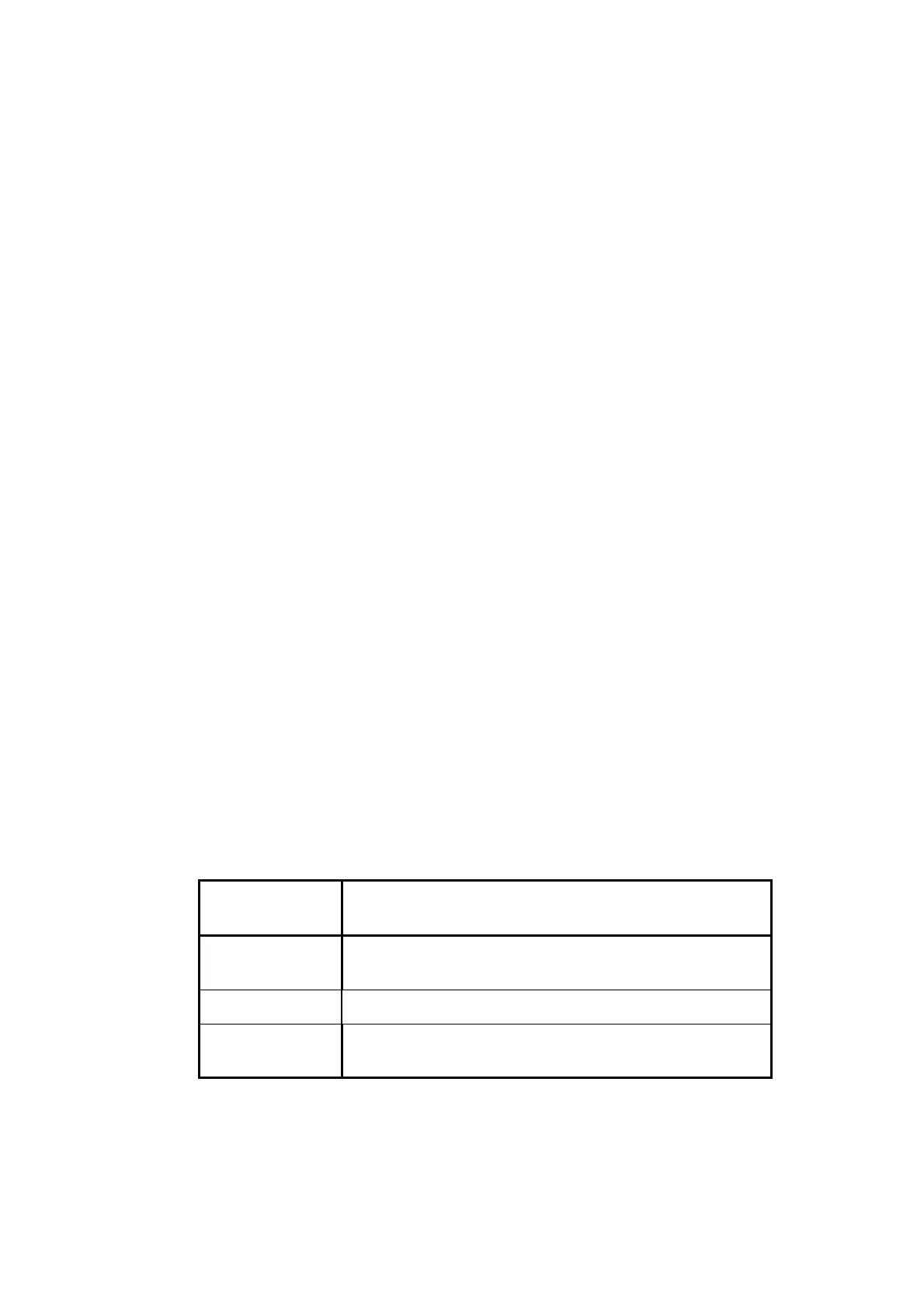
NOZZLE SIZE PRINT HEAD DISTANCE FROM PRINT
SURFACE
75 micron 12mm (0.47”) nominal, 12--30mm
(0.47--1.18”)range
60 micron 12mm (0.47”) nominal, 5--20mm (0.2--0.79”) range
40 micron
(Pinpoint)
6mm (0.24”) nominal, 2--12mm (0.08--0.47”) range
Theprintheadmustbemountedperpendiculartotheprintingsurface.
The distance between print head and print surface is optimised to the
 Loading...


