REPAIR
8--22 27080 Issue 1 Sept 98
Replacement is the reverse procedure.
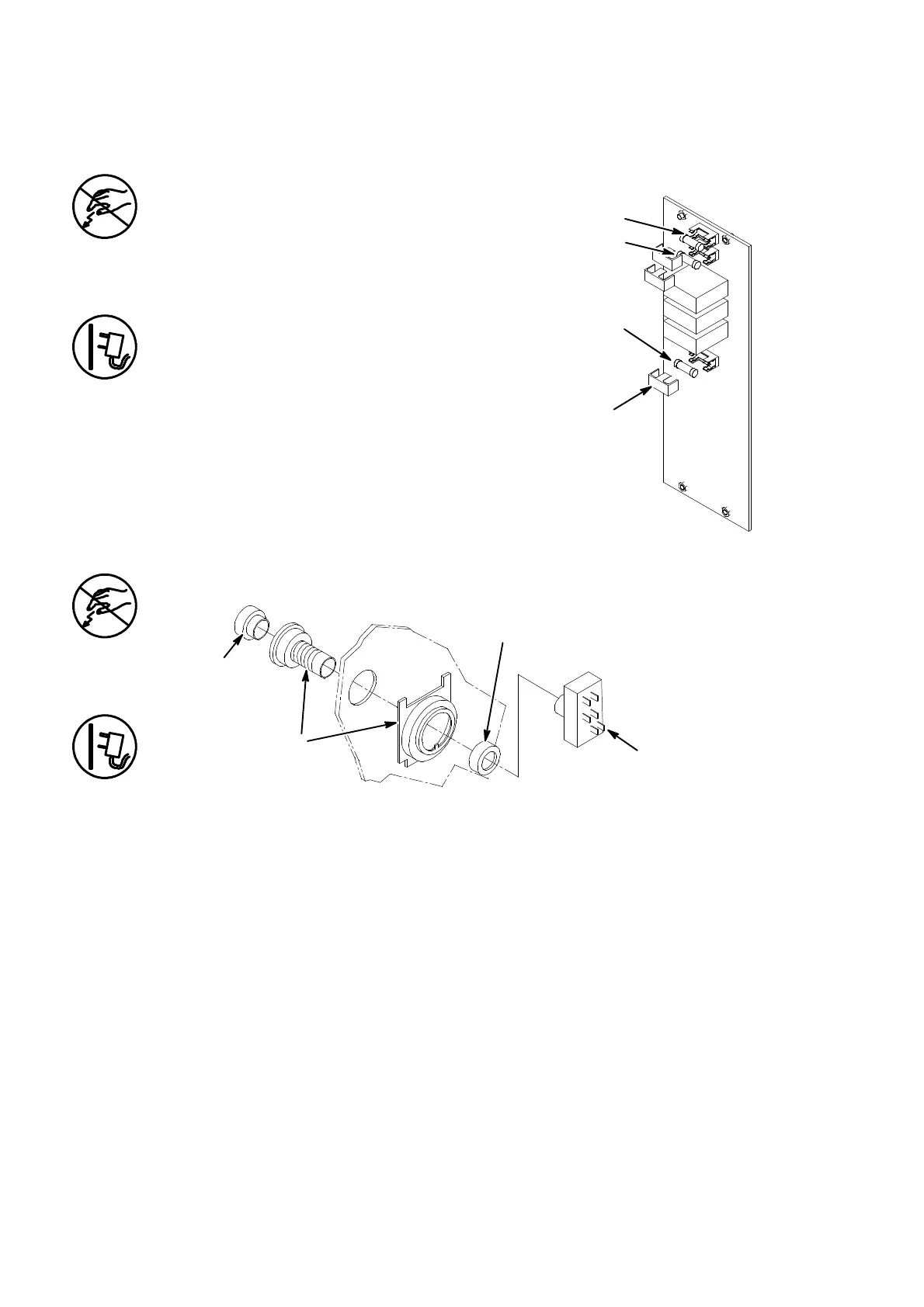
Fuse Replacement
The power must be removed and the
electronics compartment open.
The power fuses are to be found on the
External Interface PCB. Fuses F1 and F3
are 4A(T) power fuses. Fuse F2 is the
alarms contacts 1A(T) fuse. Each fuse is
protected by a small cover.
(1) Pull off the fuse cover.
(2) Pull the fuse out of the fuse holder.
(3) Push a replacement fuse into the
fuseholder and replace the cover.
Power Switch and External Connector Replacement
Power Switch Replacement
MG0175--1
Switch
Contacts
Ring Nut
Switch
Lens
The power must be removed and the electronics compartment open.
(1) Pull the rectangular block of switch contacts off the switch.
Carefully transfer the wiring from the old switch contacts to the
new switch contacts.
(2) Unscrewthe ringnutandremovetheswitchfromthecabinetside.
(3) Push the new switch lens into the new switch, then fit the switch
to the cabinet as shown. Secure with the ring nut.
(4) Push the new switch contacts onto the switch.
Replacement is the reverse procedure.
The external connectors are replaced using conventional methods.
Fuse
Replacement
Fuse F1
Fuse F3
Fuse F2
Fuse
Cover
MG091--1
 Loading...


