REPAIR
8--26 27080 Issue 1 Sept 98
PCB Assembly out of the slotted fixing holes and pull forward as
a single assembly.
(2) Remove all connectors from the Control PCB Assembly and
remove the PCB Assembly from the cabinet.
CAUTION HVwiringmustgoround,notoverorunder,theControl
PCB Assembly.
Replacement is the reverse procedure.
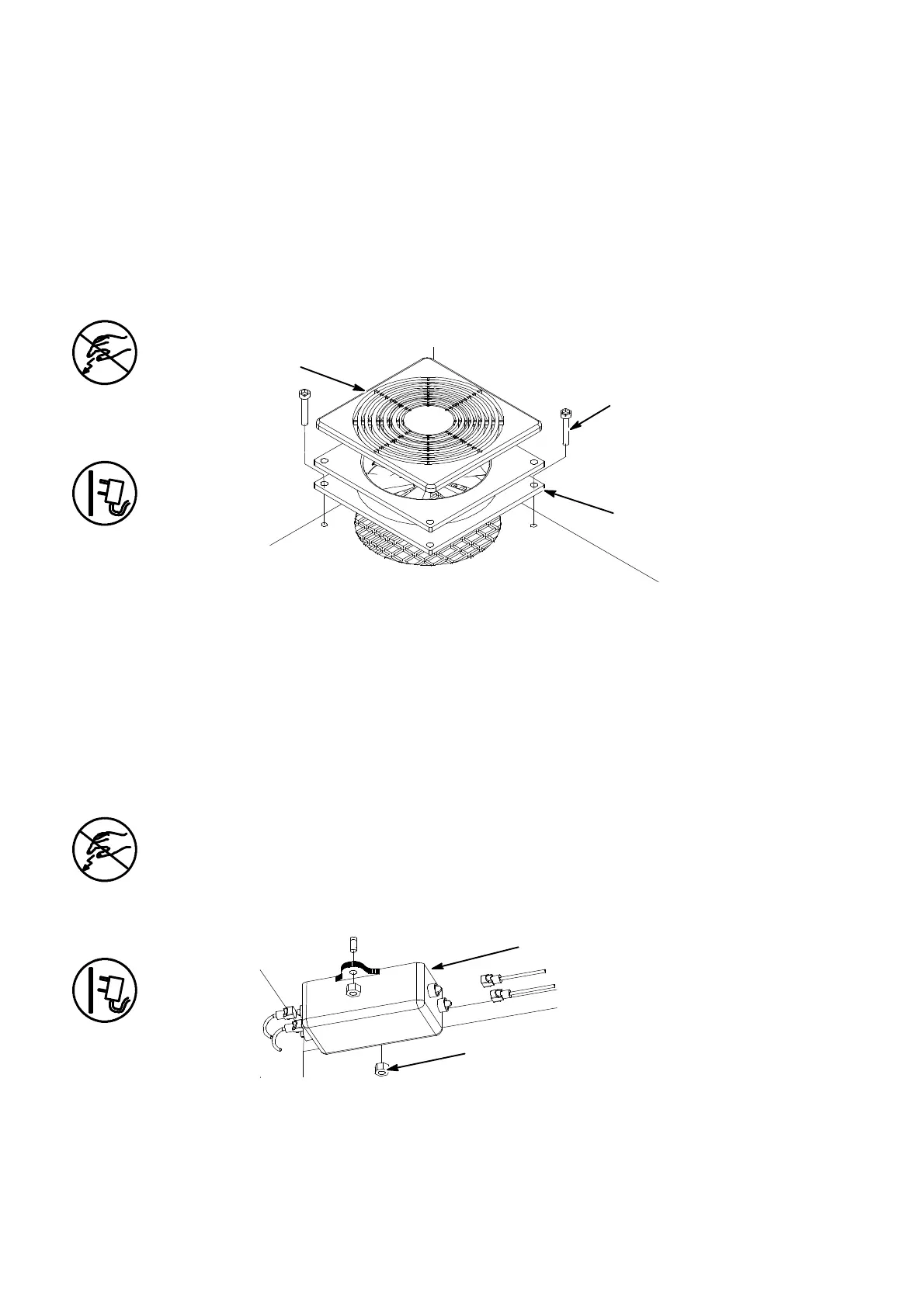
Fan Replacement
Fan Replacement
Fan
Fixing Screws
Finger Guard
MG008--2
The power must be removed and the electronics compartment open.
(1) Inside the upper compartment,disconnect the fan connectorfrom
the External Interface PCB.
(2) Loosen the two securing screws and remove the fan, finger guard
and securing screws as a single assembly.
(3) Pull the finger guard off the fan (the guard is heldby four barbs).
Replacement is the reverse procedure.
Power Filter Replacement
The power must be removed and the electronics compartment open.
(1) Remove the fixing nuts and lift away the filter.
(2) Carefully transfer the wiring to the new filter.
Power Filter Removal
Fixing Nuts
Filter
(3) Discard the old filter and fit the new filter with the fixing nuts.
 Loading...


