APPENDIX B : COMPRESSOR DRIVEN AIRDRYER
B--30 20950 Issue 1 April 98
Main Switch Replacement
WARNING: The airdryer must be switched off and power
removed.
The door must be open.
(1) Loosen the screwinthecenter of thered outerhandleandremove
the handle.
(2) Intherecesspreviouslycoveredbytheredhandle,removethetwo
fixing screws securing the switch body.
(3) Inside the cabinet, pull the switch body forward sufficiently to
remove the wiring connections.
Re--assembly, with a new switch, is the reverse procedure.
PCB Removal and Replacement
WARNING: The airdryer must be switched off and power
removed.
The door must be open.
Note: The PCB contains settings that should be checked before fitting.
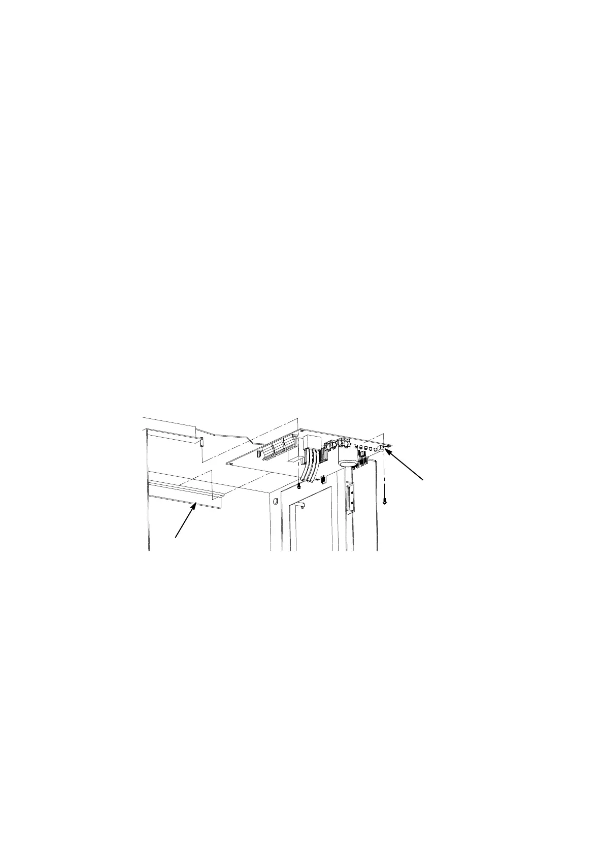
PCB
(Issue 2)
Guide
Printed Circuit Board Removal (Front View)
AD007_2
(1) NotethelocationofthewiringconnectorsonthePCB,andremove.
(2) Remove the two nylon screws near the outer edge of the PCB and
remove the PCB.
(3) To replace the PCB, fit the PCB into the cabinet, ensuring that the
backedgeofthePCBislocatedcorrectlyintheguideonthecabinet
wall.
(4) Refitthenylonfixingscrews,ensuringthatthePCBisstillproperly
located in the guide.
(5) Refit the wiring connectors (as noted in step 1).
 Loading...


