REPAIR
27080 Issue 1 Sept 98 8--25
(3) Remove thefour securingscrewsandlift awaythe LCDassembly,
disconnecting the red--and--black cabling by pulling out the
connector on the Front Panel PCB.
Replacement is the reverse procedure.
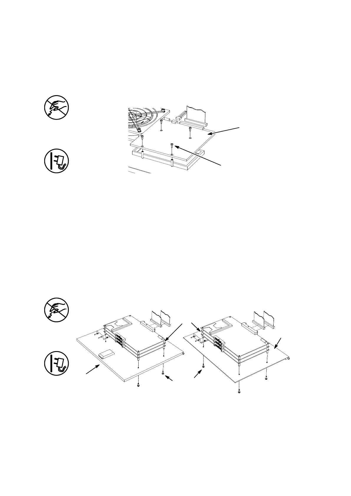
Ink System interface PCB Replacement
Ink System
Interface PCB
Fixing Screws
MG011--1
The power must be removed and the electronics compartment open.
(1) Inside the lower ink system compartment, remove the connectors
from the underside of the Ink System Interface PCB.
(2) In the upper compartment, disconnect the flat cables from the
Control Board Set connected to the Ink System Interface PCB.
(3) Remove the four securing screws and lift away the Ink System
Interface PCB together with the flat cables.
(4) RemovethecablesfromtheInkSystemInterfacePCBandretainfor
future use.
Replacement is the reverse procedure. Reconnect the ink system
connectors.
Control PCB Assembly Replacement
Printer Control PCB Assembly Replacement
Control PCB
Assembly
Fixing
Screws
Cover
MG012--1
A1010_1
Cover
A300/A200 A100
The power must be removed and the electronics compartment open.
(1) Loosen the four screws securing the three printed circuit boards
forming the Control PCB Assembly to the hinged cover. Lift the
 Loading...


