APPENDIX B : COMPRESSOR DRIVEN AIRDRYER
20950 Issue 1 April 98 B--7
DESCRIPTION
Airdryer -- General
Theairdryersystemiscontained inastainlesssteelcabinetwithadoor
fastenedbyalock. Aflangealongthetopofthecabinetprovidesfixing
holes, enabling the dryer to be fitted to the printer stand or to be wall
mounted.
CAUTION The airdryer must be mounted in the upright
position.
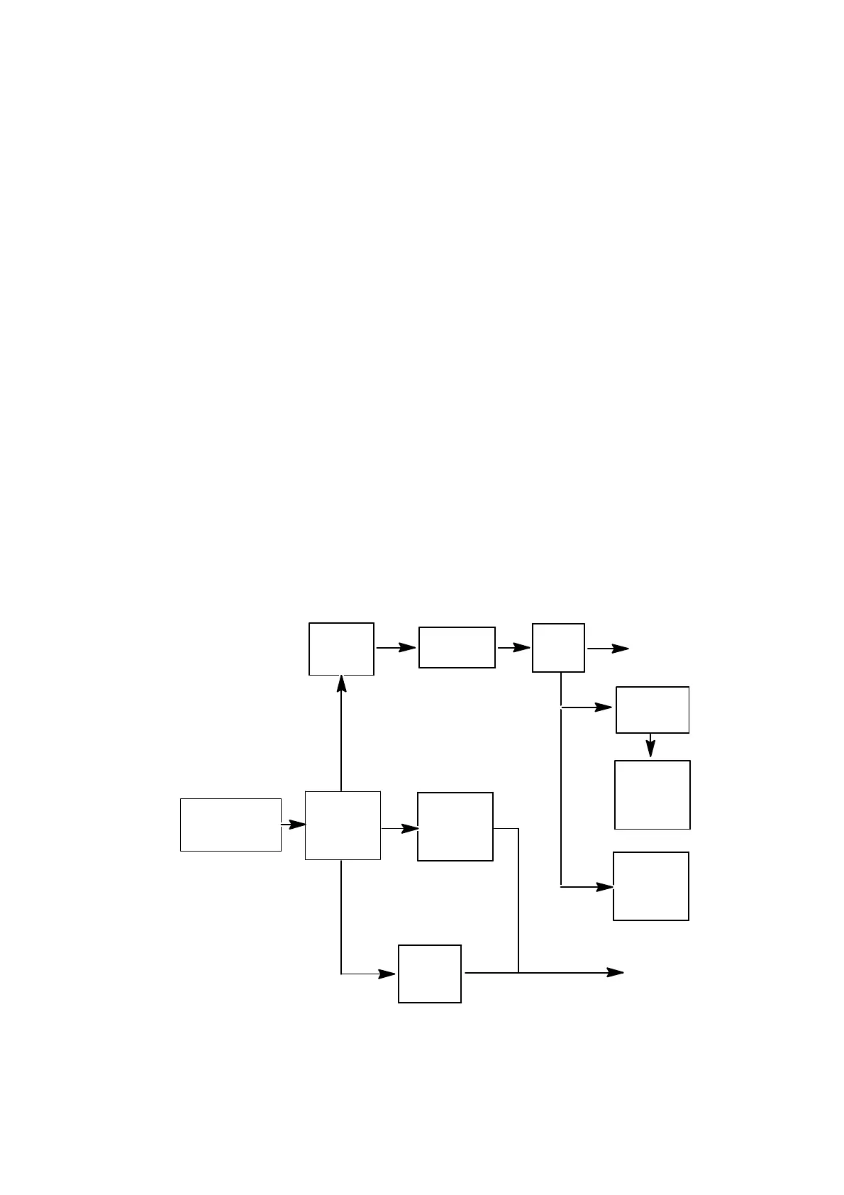
The airdryer is shown in two general views (see Pg. B--8), with the
block diagram below giving a schematic view of its operation.
Air is drawn in by the compressor and supplied at a pressure of
approximately4barto thePeltierheatsinkassembly. Increasingtheair
pressure above atmospheric pressurereduces itsdewpointand, in the
Peltier heatsink assembly, the temperature of the pressurised air is
reduced to approximately 5°C. The moisturein the air condenses and
is trapped in the Peltier heatsink assembly. The dry compressed air
then passes through a filter to a pressure regulator and a needle valve
restrictor. The regulator maintains a fixed pressure of 2bar and the
restrictor valve maintains a fixed flow rate from the airdryer of 2.0 to
2.2 litres/minute to the print head.
Compressor
Filter
Needle
Valve
Pressure
Relief
Valve
Solenoid
Valve
Clean
Air
Output
Airdryer Schematic Diagram
Humidity
Sensor
Pressure
Switch
Inline
Orifice
Pressure
Regulator
Vent
Peltier
Heatsink
Assy
 Loading...


