Rosemount Model 1195/ProPlate/Mass ProPlate
7-2
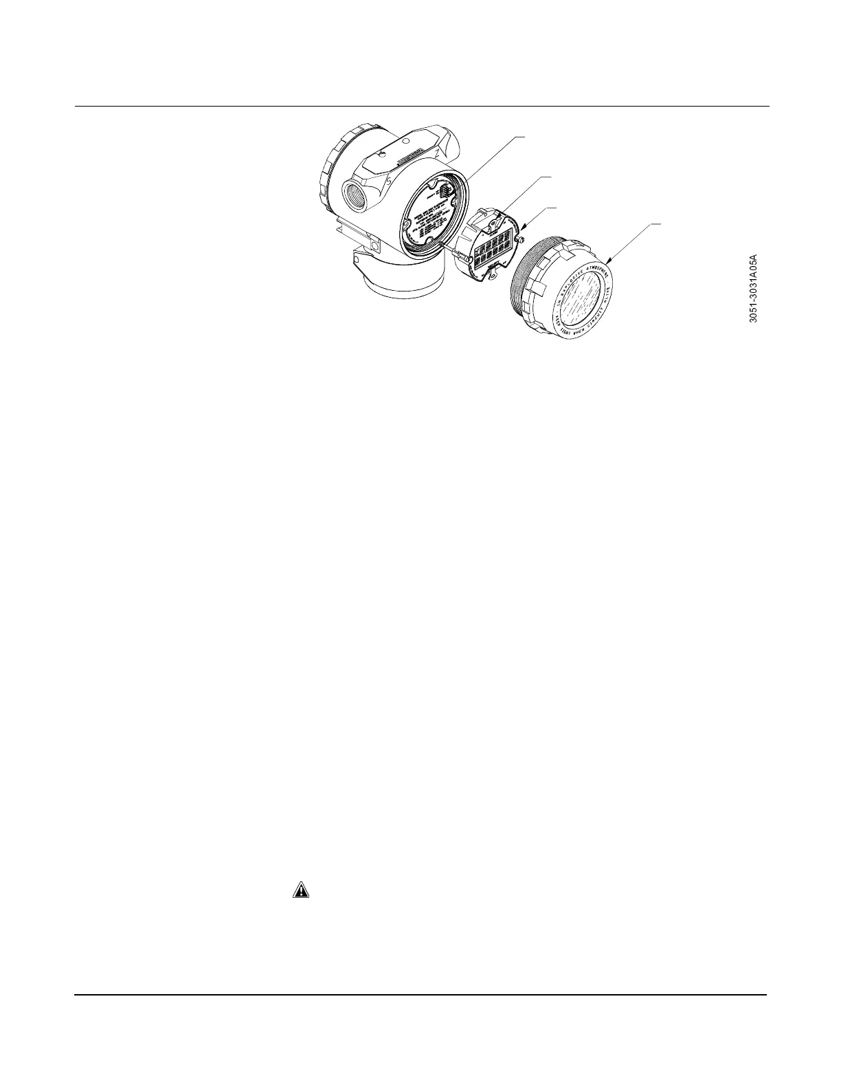
Figure 7-1.
Exploded View of the ProPlate with
Optional LCD Meter.
Installing the Meter
For flowmeters ordered with the LCD meter, the meter is shipped
installed. Installing the meter on an existing ProPlate flowmeter
requires a small instrument screwdriver and the meter kit.
The kits vary depending on the version of flowmeter electronics.
Examine the following numbers carefully to ensure you are installing
the correct kit.
For use with Shrouded Electronics Board
Meter Kits
Option M5: P/N 03031-0193-0101
Option M6: P/N 03031-0193-0111
For use with Non-Shrouded Electronics Board
Meter Kits
Option M5: P/N 03031-0193-0001
Option M6: P/N 03031-0193-0011
The meter kit includes:
• one LCD meter assembly
• one extended cover with cover O-ring installed
• two nylon standoffs
• two captive screws
• one ten -pin interconnection header
Use the following procedure and Figure 7-1 to install the LCD meter. If
the meter is an upgrade from a previous version, upgrade the
electronics board before attempting to install the meter.
1. If the flowmeter is installed in a loop, secure the loop and
disconnect power.
2. Remove the flowmeter cover opposite the field terminal side. Do
not remove the instrument covers in explosive environments when
the circuit is alive.
3. Remove the failure mode and alarm jumpers from the electronics
module, and insert them in their new positions above and below
the meter readout on the meter assembly.
Interconnecting Pins
Jumpers
(top and bottom)
LCD Meter
Extended Cover
$
$

 Loading...